


January 31, 2013
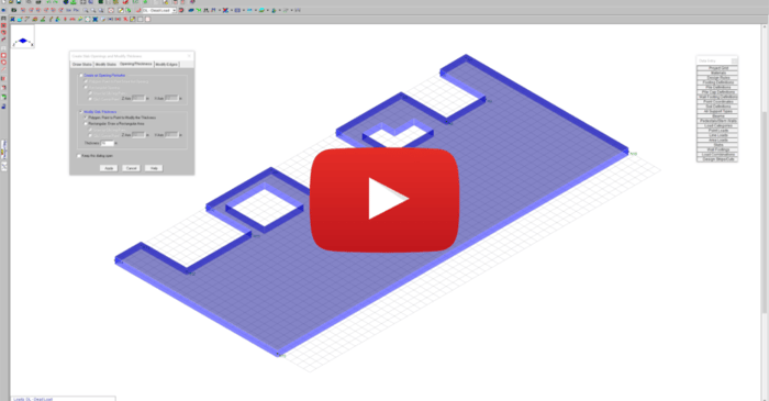
Slab Modifications in RISAFoundation
This video shows how slab modifications can used to add an opening or change the thickness of a portion of the slab in RISAFoundation.
This video shows how slab modifications can used to add an opening or change the thickness of a portion of the slab in RISAFoundation.
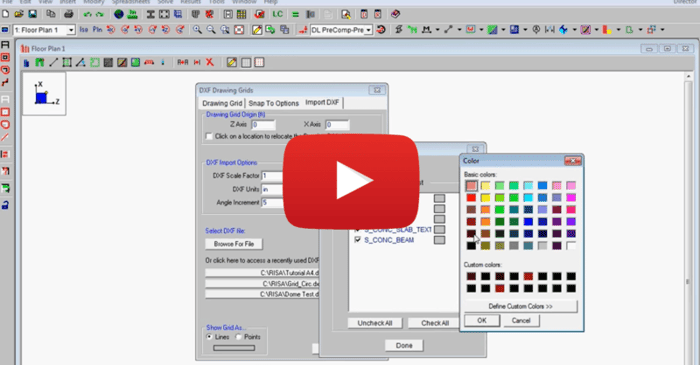
This video shows how to import a DXF as a drawing grid in RISAFloor. To do this, you can save any drawing file as a DXF file format and import points, lines, polylines, arcs and circles into RISAFloor. This gives you the ability to create your own drawing grids with complex geometries and use this...
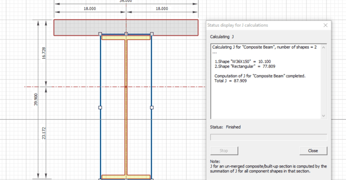
RISASection v2 includes updated torsional shape properties for a more accurate analysis. Check out the video below for more information:
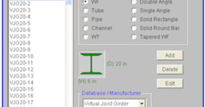
The Steel Joist Institute (SJI) has recently put together a Virtual Joist Girder table which converts common joist sizes into equivalent wide flange beams. This topic describes how to use these Virtual Joist Girders within the RISAFloor program.
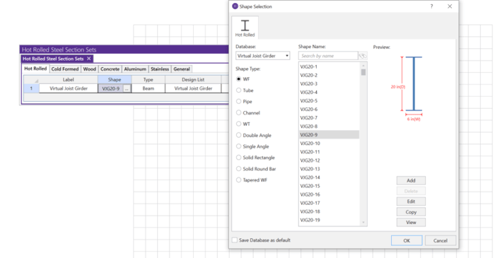
The Steel Joist Institute (SJI) has developed a Virtual Joist Girder table which converts common joist sizes into equivalent wide flange beams for use in RISA-3D.
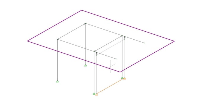
Let’s consider the example of the frame shown below. Suppose there is a diaphragm present at the framing level, and that the wall shown is intended only to handle the lateral loads. In reality the columns will be in-line with the wall, and the cantilever beams will pass over the wall without...

RISA programs are Windows-based and require a Windows operating system to run. Although RISA software does not operate natively on macOS, it is compatible with virtual machines that run Windows OS on your Mac. Below are the steps to get RISA up and running smoothly:

RISAFoundation includes a footing element which is represented by a single node. A frequent question that arises is how to apply multiple point loads to a single footing, but at different locations. This can be done with or without corresponding pedestals, but for the example below multiple...
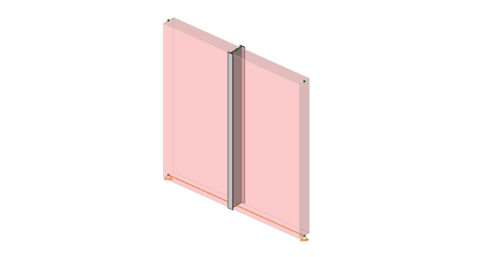
While RISA-3D does not currently have pilaster design, there are still plenty of situations where you would want to have a column embedded within a wall. The idea behind this is that the column handles the gravity loads for any beams which frame into it, while the wall handles lateral loads. No...