


 By: RISA


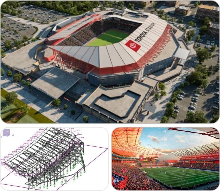
Stadium Structural Design: Crowd Loads, Retrofits, and RISA Tools
World Cup stadiums are a stress test for structural design. High live...
We often get asked: “Should I model my foundation as a slab or a spread footing in RISAFoundation?” While both are valid options, they use very different analysis methods, and the results can vary accordingly.
In this article, we’ll walk through a side-by-side comparison, using the same modeled conditions to highlight how the results differ — and why.

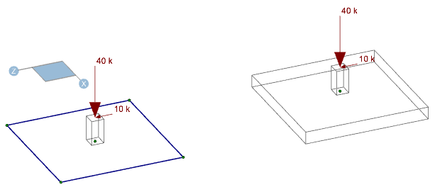
To keep things consistent, we modeled a single condition in two ways: once with a spread footing and once with a mat slab.
Mat Dimensions: 10' x 10' x 1'
Pedestal: 1' x 1' x 2'
Loads Applied:
40 k vertical dead load
10 k lateral dead load
15 k lateral wind load
Soil Overburden: Set to 0 for both elements
Slab Mesh Size: Refined below default for more detailed results
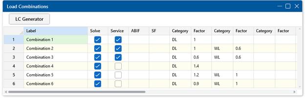
Load Combinations: A basic set used for clarity (see screenshots in RISAFoundation)
|
Feature |
Spread Footing |
Slab Element |
|
Analysis Type |
Rigid body |
Finite Element Analysis (FEA) |
|
Support Model |
Single support point |
Compression-only springs (based on subgrade modulus) |
|
Mesh Behavior |
No submesh |
Submeshed into smaller plate elements |
Lever Arm for Lateral Loads
Spread Footings: Full pedestal height + full footing thickness
Slabs: Full pedestal height + half slab thickness (to slab centroid)
*Except for the overturning slab stability check where full slab thickness is included.
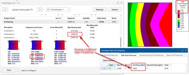
Because of the analysis method:
Spread Footings produce a linear bearing pressure distribution (rigid body assumption)
Slabs show a curved pressure profile, influenced by relative stiffness of slab and soil
Changing the subgrade modulus impacts slab soil pressure (since it impacts the stiffness of the compression only springs), but not spread footing soil pressure (since it's considered a rigid body). However, spread footing deflection will change with an updated subgrade modulus.
Spread Footings and Slabs differ in how they consider the forces either stabilizing or destabilizing:
Spread Footing: Look at every component (X, Y, Z, MX, MY, MZ) of every load individually to determine whether it's stabilizing or destabilizing.
Slab: Look at each load category to determine whether the net effect of that load category is stabilizing or destabilizing.
This distinction can lead to different safety factors, even when the same loads are applied.
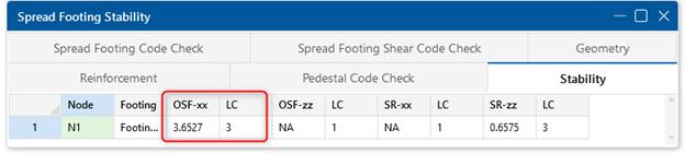
Sample Calculation (Load Combo: 0.6D + 0.6WL)
Spread Footing
Overturning Moment = (0.6 × 10k + 0.6 × 15k) × 3 ft = 45 k-ft
Resisting Moment = 0.6 × (40k + 14.79k) × 5 ft = 164.37 k-ft
Safety Factor = 164.37 / 45 = 3.65
Slab Element
Overturning Moment = 0.6 × 15k × 3 ft = 27 k-ft
Resisting Moment = [0.6 × (40k + 14.79k) × 5 ft] – [0.6 × 10k × 3 ft] = 146.37 k-ft
Safety Factor = 146.37 / 27 = 5.42
Notice: The lateral dead load increases overturning in the spread footing case but is subtracted from resisting moment in the slab case. Same loads, different logic.
More here:
🔗 Footing Overturning Help
🔗 Slab Overturning Help
When the load resultant falls outside the support area, the behavior differs:
Spread Footings: Solution completes but displays a red warning in the detail report— “calculations not available”
Exception: Spread footings under ultimate-level combos have special logic for moment/shear demands in these conditions. See Footing Overturning Help for more information on this exception.
Slabs: Solution cannot complete — error message: “model instability detected”
The soil bearing profiles discussed earlier also affect shear and moment demands, but a more significant difference is how the program determines where to check them.
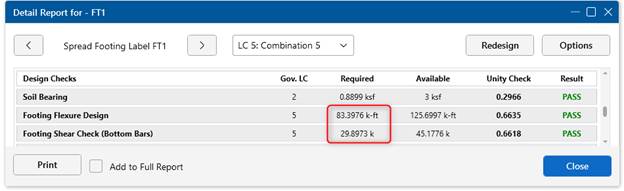
Spread Footings
Moment checked at face of pedestal
One-way shear checked at a distance d (footing thickness minus rebar cover and one bar diameter) from the face of pedestal
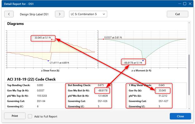
Slabs (Design Strips)
You must draw design strips
Slab checks the worst case along each strip
Pedestal location not considered — can result in conservative internal demands
Generally the slab may have higher shear/moment demands compared to spread footings (when design strips are drawn continuously over pedestal locations), as demonstrated in this example.
For Reference:
Even when matching rebar size, spacing, and cover in the inputs, the rebar placement differs slightly:
Spread Footings: Rebar placed on top of transverse bars, adding height
Slabs: Design strips assume rebar is placed at cover depth only
This may explain small discrepancies in calculated bending moment capacities. Adjusting cover settings for design strips on a per-direction-basis (N/S or E/W) may help align them more closely.
|
Feature |
Spread Footing |
Slab (via Pedestal Element) |
|
Where to Find |
Footing Shear Check in Detail Report |
Pedestal Element Detail Report |
|
Moment Considered? |
❌ Not yet |
✅ Yes, moment included in check |
|
Recommendation |
When moments are large (such as from large shears and/or tall pedestals), using the pedestal element on slab would give more accurate punching shear results. |
|
Both spread footings and slabs are valid and powerful tools in RISAFoundation. The best choice depends on:
The type of behavior you want modeled (rigid vs. flexible)
Whether punching shear with moment needs to be checked
The level of detail you need in soil pressure and slab response
Understanding the underlying analysis differences helps ensure your model produces safe, accurate, and efficient results.
World Cup stadiums are a stress test for structural design. High live...
New to RISAFloor and RISAFoundation is the ability to exclude results...

When RISA-3D will not launch, cannot see a cloud license, or suddenly...