


August 31, 2010
How Are Wind Loads Generated for Sloped Roofs?
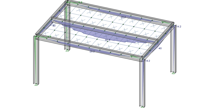
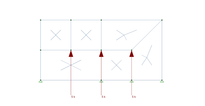
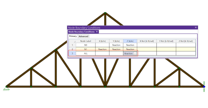
RISAFloor is capable of automatically generating the wind loads on sloped roofs. Let’s look at an example of this with the model below:
RISAFloor is capable of automatically generating the wind loads on sloped roofs. Let’s look at an example of this with the model below:
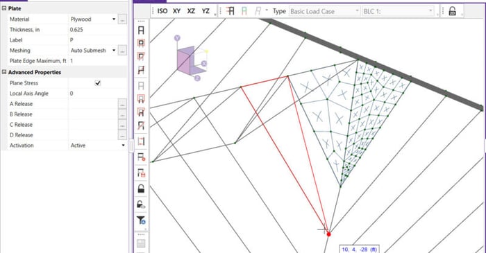
In standalone RISA-3D models (those not integrated from RISAFloor), Semi-Rigid diaphragms cannot be directly defined. Only the Rigid diaphragm type is available by default. To create a semi-rigid diaphragm in a standalone RISA-3D model, users must define plate elements manually. If you’re dealing...
In order to understand the interaction between plates and members it is important that you know the basics of Physical Members and Plate Connectivity. Remember that plates only connect to other elements at their corners, and you will instantly recognize why the model below will not work as intended.
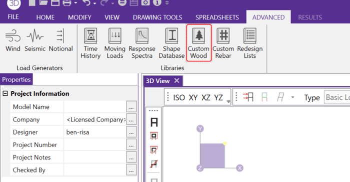
In RISA-3D and RISAFloor, the entire NDS species list is available as well as glulam materials but you may need to design a wood product that is not available in the program.
To best understand how plates interact with each other you must first understand the concept of Physical Members. The important thing to keep in mind is that plates are not physical members. A plate is defined using either three or four joints, and it only connects to other plates at those joints....
When you have a deep column, it is necessary to model the beam so that it connects to the face of the column. This results in an eccentricity at the joint. RISA-3D offers two ways to model this eccentricity.
There are four different values for Unbraced lengths in RISA-3D, RISA-2D and RISAFloor. Two are for axial calculations and two are for bending calculations.
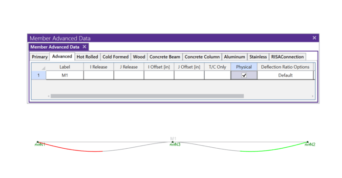
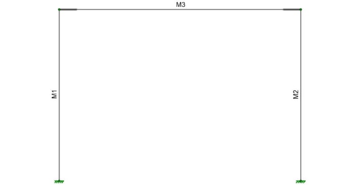
Members (beams, columns, braces, etc.) are defined in RISA by an I-Node and a J-Node. While you and I see a beam occupying physical space between two columns, most programs see a line between Point I and Point J. This is known as a non-physical member. See the image below:
If you have ever tried to solve a two-dimensional model in RISA-3D, you have ultimately run into instabilities in your model because your model has no out of plane restraint.