June 22, 2010
How to Create an Engineered Wood Material
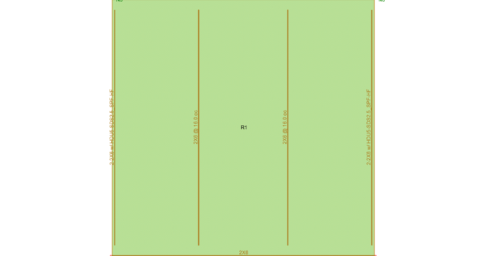
In RISA-3D and RISAFloor, the entire NDS species list is available as well as glulam materials but you may need to design a wood product that is not available in the program.
In structural engineering, few design challenges are as rewarding—or as unforgiving—as the tall building. While gravity systems and code checks form the backbone of any structural project, once a structure rises beyond ten or fifteen stories, a shift occurs. Wind and seismic forces begin to dominate. Story drift and torsional irregularities become non-negligible. Load paths grow increasingly indirect. And design decisions, if not carefully made early on, can have exponential consequences higher in the structure. Tall buildings are not simply “bigger” versions of short ones. They behave differently. And understanding those differences is essential for any engineer working in an urban environment where building vertically is often the only viable path forward. Modeling for Reality, Not Just Code The foundation of any successful tall building design lies in the model—its assumptions, resolution, and degree of abstraction. Many engineers begin with simplified representations: rigid diaphragms, idealized connections, and linear material properties. This is practical and often sufficient for early design phases. But as the building increases in height and complexity, those assumptions may start to mask critical behaviors. Semi-rigid diaphragm modeling, for instance, allows engineers to capture in-plane flexibility of floor systems—especially important in buildings with irregular cores, open floor plans,…
Read More
In RISA-3D and RISAFloor, the entire NDS species list is available as well as glulam materials but you may need to design a wood product that is not available in the program.
To best understand how plates interact with each other you must first understand the concept of Physical Members. The important thing to keep in mind is that plates are not physical members. A plate is defined using either three or four joints, and it only connects to other plates at those joints....
When you have a deep column, it is necessary to model the beam so that it connects to the face of the column. This results in an eccentricity at the joint. RISA-3D offers two ways to model this eccentricity.
There are four different values for Unbraced lengths in RISA-3D, RISA-2D and RISAFloor. Two are for axial calculations and two are for bending calculations.
Members (beams, columns, braces, etc.) are defined in RISA by an I-Node and a J-Node. While you and I see a beam occupying physical space between two columns, most programs see a line between Point I and Point J. This is known as a non-physical member. See the image below:
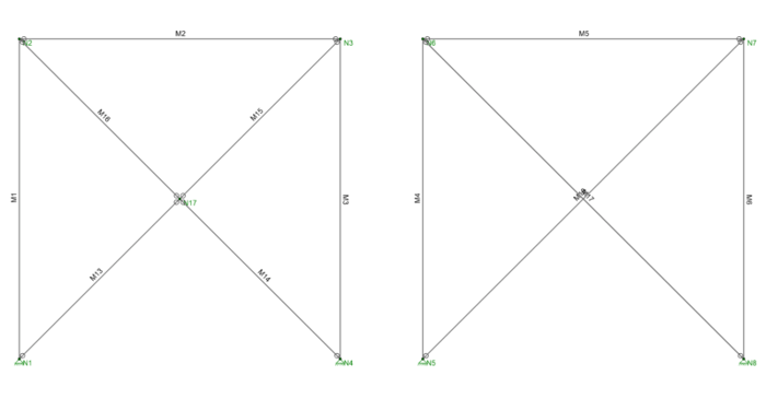
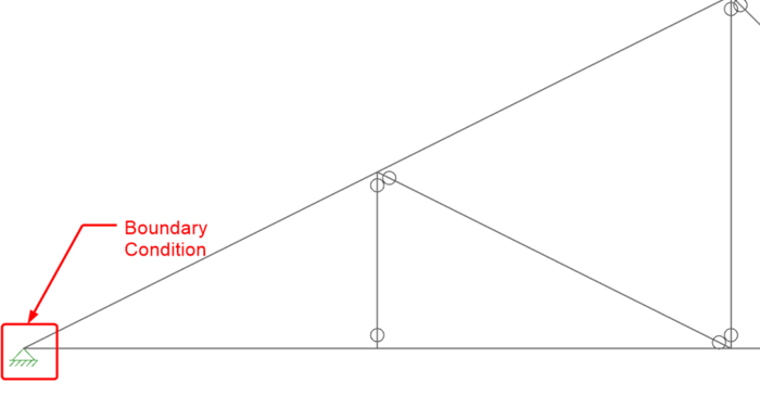
If you have ever tried to solve a two-dimensional model in RISA-3D, you have ultimately run into instabilities in your model because your model has no out of plane restraint.
Do you get an instabilities warning when you’re trying to do a simple 2D model in RISA-3D?
Our monthly "Structural Moment" newsletter is the best way to keep up with RISA’s product updates, new releases, new features, training events, webinars and more...