April 8, 2015
How can I transfer my slab design from RISAFloor ES onto drawings?
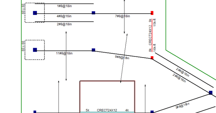
The ability of RISAFloor ES to design rebar for two way concrete slabs is powerful. Such designs are made much more powerful when they can easily be conveyed on construction drawings.