July 14, 2015
How to Import a Seismic Moment Connection into RISAConnection
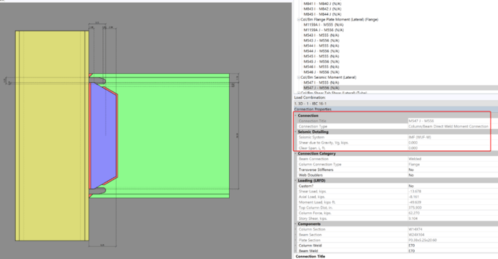
Design for seismic connection detailing is now available in RISAConnection and you can use the connection rules within RISAFloor and RISA-3D to export a RISAConnection model. The integration will import the connection forces (and seismic detailing results) into RISAConnection for seismic moment...