By: Admin
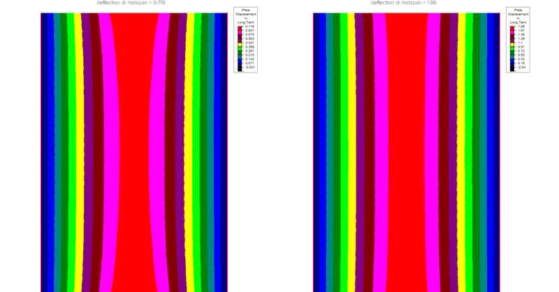
Why does my slab deflection increase using ACI 318-19?
Since the release of RISAFloor v15 and ADAPT-Builder v20, both which...
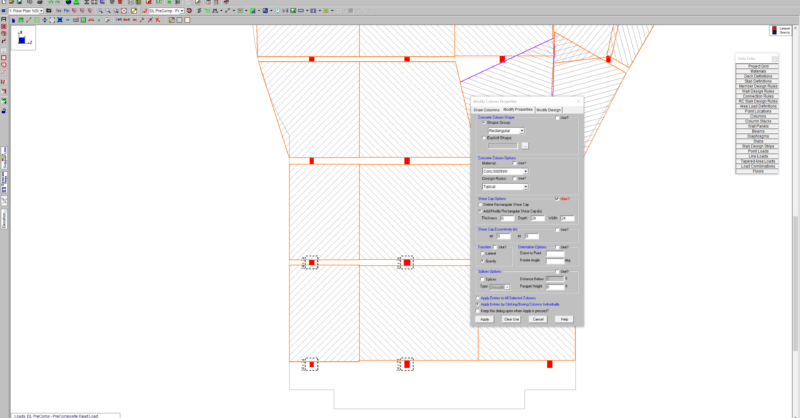
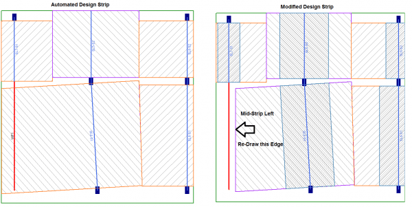
In RISAFloor ES, you draw a support line from support point to support point to define the Design Strips. The program will automatically create Design Strips based on the tributary width. When you have walls in the model, it is often a question of how you draw in the support lines.
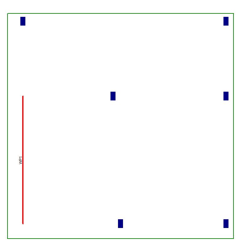
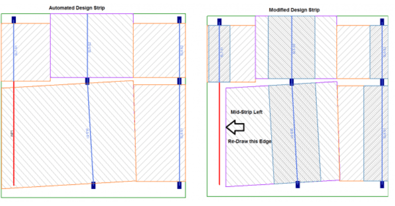
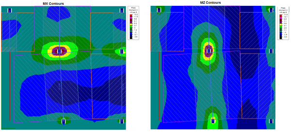
Design strips are drawn over the slab as design regions that capture the forces and are most optimally bound by lines of zero shear transfer. The best way to understand your model and where to place design strips is to examine the moment contours. In this simple model with a wall along one edge, it can be seen that there is almost zero moment over top of the wall.
Since there is no moment over the top of the wall, it would not be advised to draw a support line directly over top of the wall. The adjacent design strip will automatically be generated to extend to the slab edge. However, using your engineering judgment, you can control the size of the strip by sliding the Mid-Strip Left Edge to accommodate the flow of forces in your slab.
Since the release of RISAFloor v15 and ADAPT-Builder v20, both which...
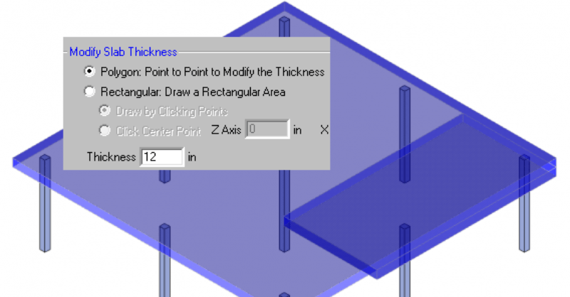
RISAFloor ES allows you to model concrete slabs of any thickness....