By: RISA
CSA S16-14 Canadian Steel Code now Available
RISA-3D now supports hot rolled steel design for the Canadian market...
Key Takeaways
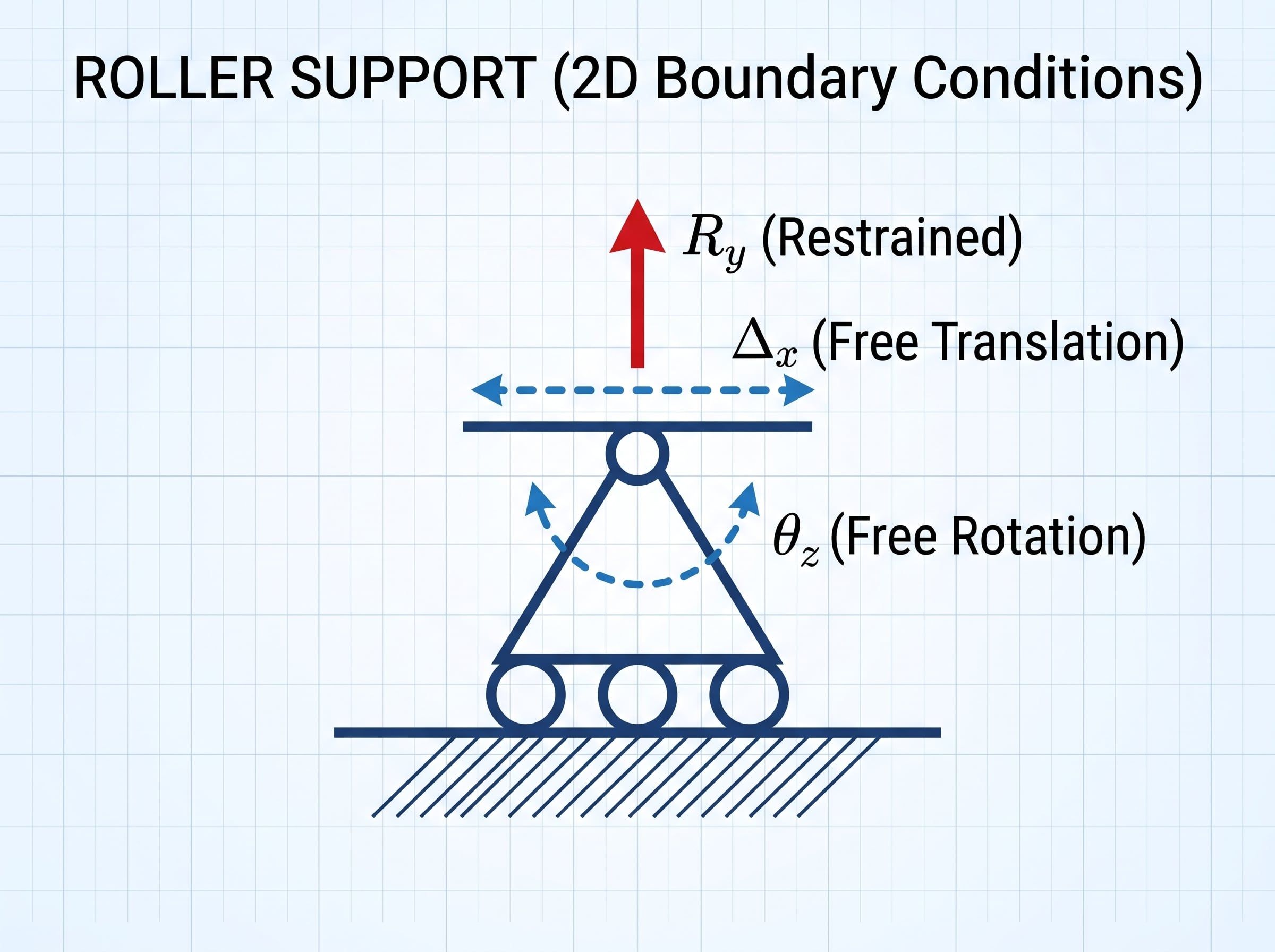
In structural mechanics, a roller support is an idealized boundary condition that resists movement in only one direction, perpendicular to the surface it rests on, while allowing for displacement parallel to that surface and free rotation about its joint.
Unlike fixed or pinned supports, a roller support cannot develop horizontal reactions (Rx = 0) or bending moments (M = 0). If applied vertically under a standard beam, the support generates a single normal reaction force (Ry) to counteract vertical gravity loads.
The decision to use a roller support comes down to controlling internal force buildup. Completely fixing every joint in a long-span structure generates internal forces that can control the design over externally applied loading.
All construction materials expand with heat and contract with cold according to their linear thermal expansion coefficient (α):
ΔL = α • L • ΔT
Consider a 150-foot structural steel bridge girder subject to a seasonal temperature swing. If both ends are pinned and fixed against horizontal translation, the displacement (ΔL) is prevented and induces axial stress:
σ = E • α • ΔT
For structural steel (E = 29,000ksi, α ≈ 6.5 x 10⁻⁶/°F), a temperature swing of 80 degrees F yields over 15ksi of axial stress across a fully restrained member. Multiplied across the cross-sectional area of a heavy plate girder, this restraint develops a large compressive force, risking member buckling or shearing anchor bolts. Installing a roller support at one end allows the member to expand and contract freely, keeping thermal stress at zero.
A beam pinned at both ends creates an internally indeterminate system where temperature changes, foundation settlement, and fabrication tolerances produce secondary stresses. Using a pinned support at one end and a roller support at the other forms an internally determinate system known as a simply supported member. Determinacy establishes straightforward, predictable load paths that are easier to verify and less vulnerable to localized failure modes.
As a beam bends under the applied load, its neutral axis deflects into a curve, pulling the endpoints closer together horizontally. A roller support shifts slightly inward to track this chord-length reduction, preventing destructive prying forces and lateral thrust against supporting columns or abutments.
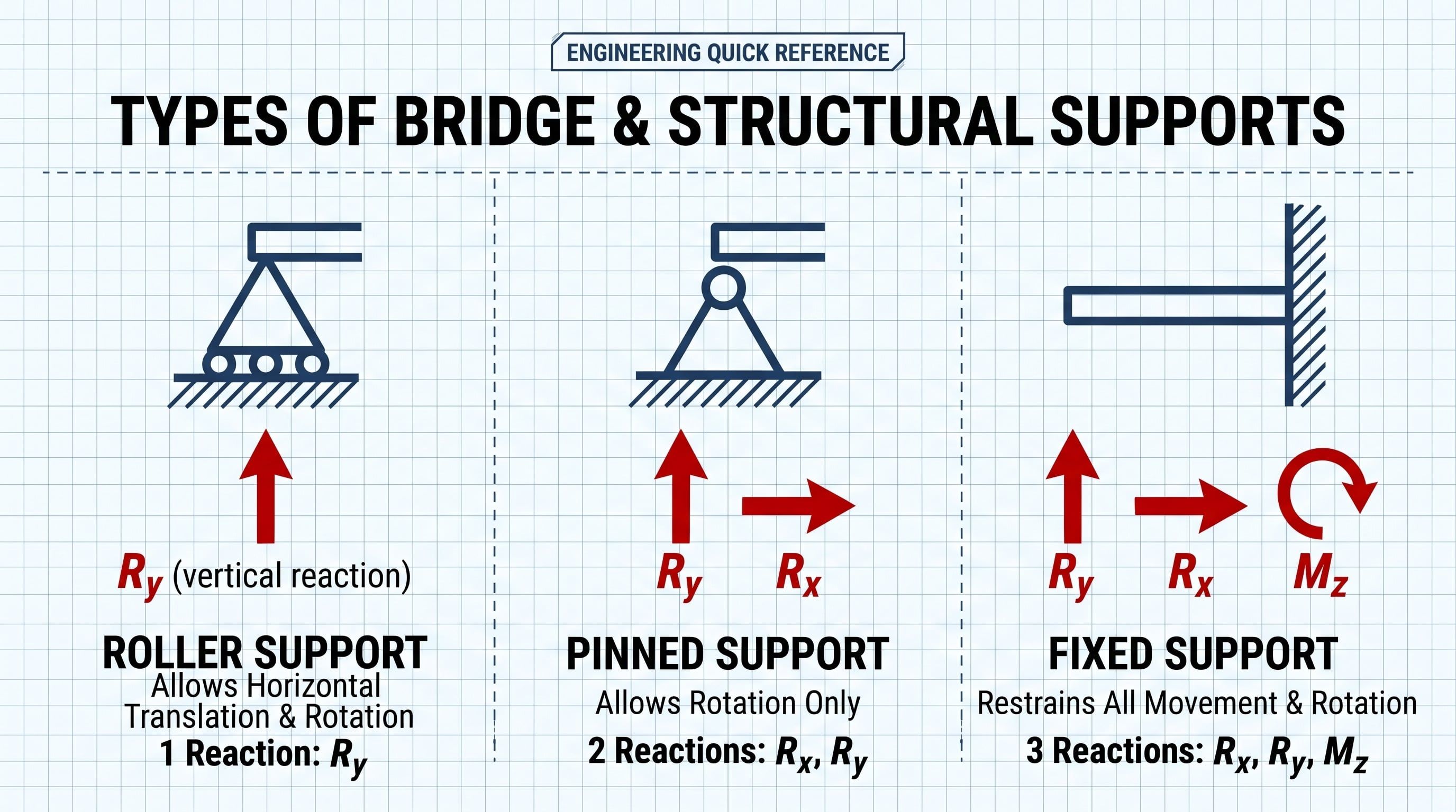
The boundary condition selected governs how forces transfer through your structure:
|
Support Type |
2D Plane Translations |
3D Space Translations |
Rotations Restrained |
Reactions Developed (2D / 3D) |
Primary Structural Uses |
|
Roller Support |
Restrains Y; frees X |
Restrains Y; frees X,Z |
None (all free) |
1 Force (Ry) in 2D (1 normal force in 3D) |
Bridge expansion ends, pipe racks, roof trusses |
|
Pinned Support |
Restrains X,Y |
Restrains X,Y,Z |
None (all free) |
2 Forces (Rx,Ry) in 2D (3 forces in 3D) |
Truss panel points, simply supported beam hinges |
|
Fixed Support |
Restrains X,Y |
Restrains X,Y,Z |
Restrains all (θ in 2D; Mx,My,Mz in 3D) |
2 Forces + 1 Moment in 2D (3 forces + 3 moments in 3D) |
Cantilever columns, moment frame bases, retaining walls |
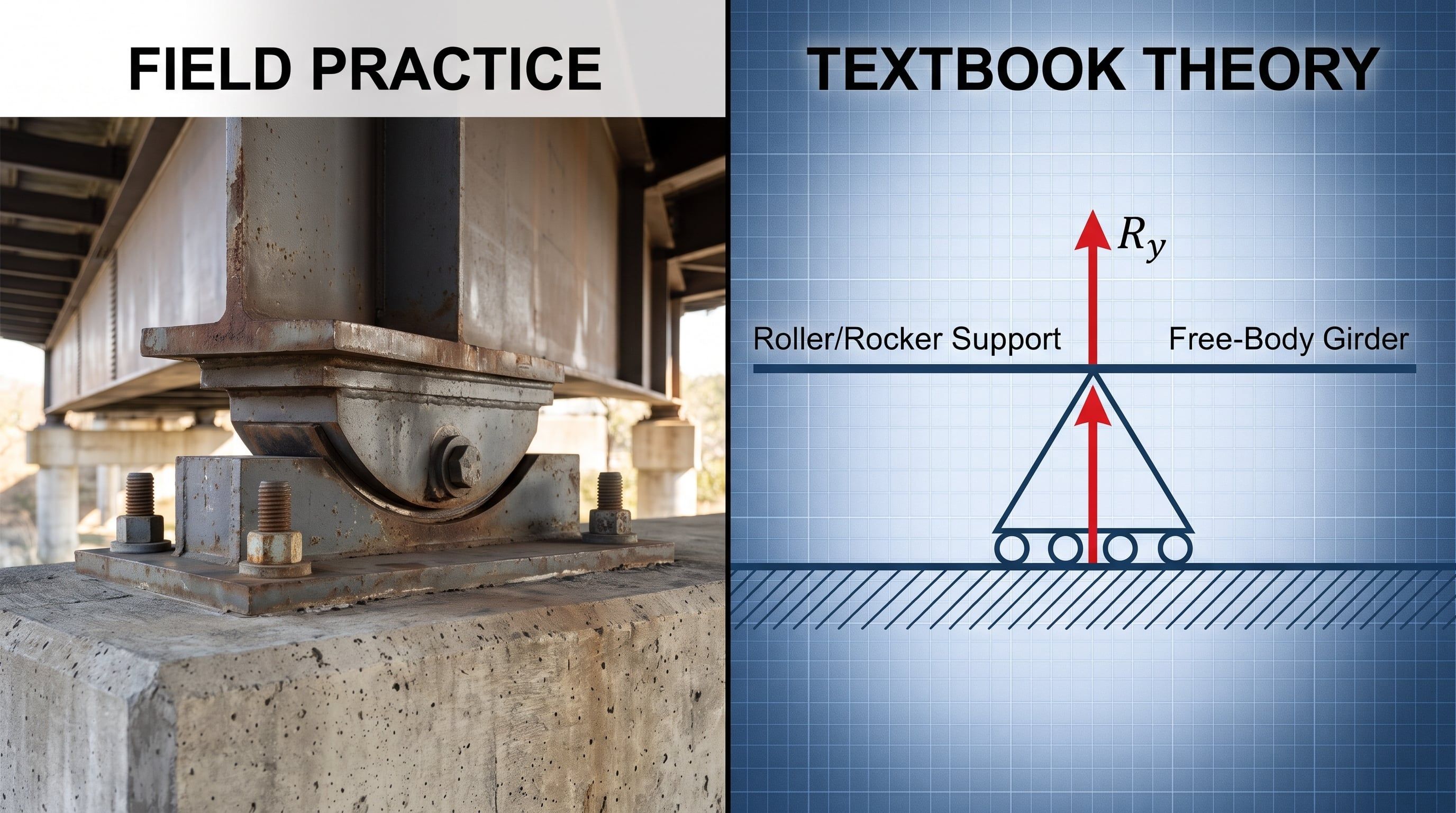
Physical roller supports rarely look like classroom textbook wheels. Structural engineers translate the kinematic concept of a roller support through specialized field connections:
Long, straight runs of steam lines, oil conduits, and chemical pipes experience large amounts of thermal expansion during operation. Engineers mount these pipelines on mechanical steel pipe rollers or cradle slides to let the pipes move axially without overstressing connected pumps, valves, or pipe elbows.
Large-span steel roof trusses for gymnasiums, hangars, and stadiums rest on slotted-hole bolted connections or Teflon slider pads along one perimeter wall. This frees the truss to expand due to solar heat gain without causing masonry walls or perimeter columns to go out of plumb.
Modern seismic design often decouples a building from ground acceleration using friction pendulum bearings or roller-based isolation systems. These mechanisms let the foundation translate horizontally beneath the superstructure during an earthquake, reducing base shear transmission.
When transitioning from structural concepts to FEA software like RISA-3D, boundary condition definitions must accurately reflect real-world mechanical releases.
To model a standard horizontal roller support in software:
A structure must have sufficient external boundary restraints to maintain static equilibrium. Assigning roller supports to all boundary nodes leaves the system with no resistance against lateral loads (such as wind or seismic forces), triggering model instability errors during analysis. A stable simply supported system requires at least one pinned support to resist lateral translation.
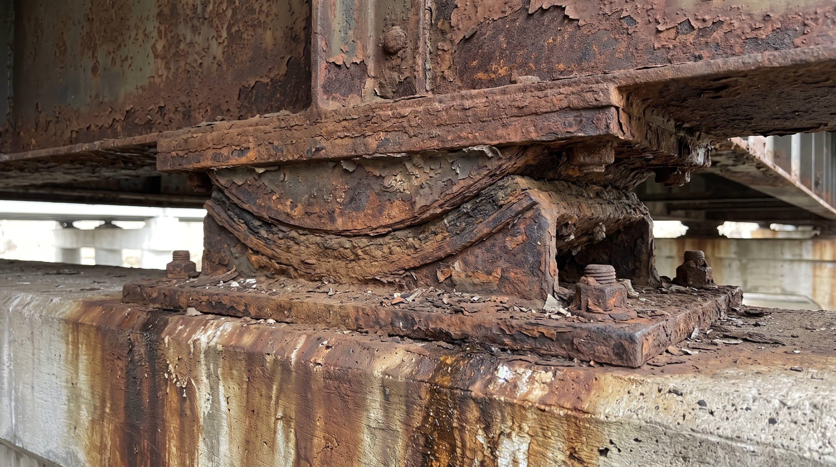
Real-world rollers and sliding bearings are not frictionless. Over time, environmental exposure and lack of maintenance cause steel rockers to corrode and freeze. A damaged roller transitions into a pinned support, introducing unplanned horizontal shear forces into the connection. When evaluating existing structures, engineers must verify that bearing movement remains unrestrained or account for friction-induced shear in the support check.
A firm grasp of roller support mechanics ensures a structural system flexes where needed and carries gravity loads safely to the foundation. Strategic roller boundary conditions shield bridges, roofs, and industrial plants from destructive thermal fatigue and uncontrolled stress spikes.
RISA-3D offers preset boundary conditions, including roller, pinned, and fixed, checks reaction forces, and verifies deflection limits directly within your analysis workflow. Start your free trial today to transition away from manual degree-of-freedom tracking and streamline your structural models with reliable, code-compliant tools.
RISA-3D now supports hot rolled steel design for the Canadian market...
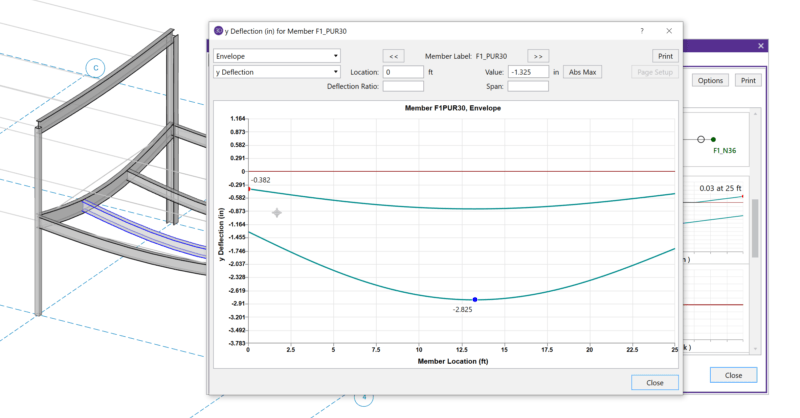
When solving a RISA-3D model with hot rolled steel members under the...