How to Use Multi-Period Response Spectrum Data for Seismic Load Generation?
With the adoption of ASCE 7-22, the concept of a multi-period response...
Key Takeaways
Pinned supports provide absolute positional stability by restricting vertical and horizontal movement while allowing members to rotate freely, effectively eliminating bending moments at the connection. This "pivot" behavior enables structures to "breathe" during thermal expansion and ensures material efficiency in trusses, provided the global system is stabilized by bracing or shear walls. In structural software, these are modeled using fixity codes that lock translations as reactions while releasing rotational degrees of freedom to prevent unintended structural instability.
In structural engineering, a pinned support (frequently called a hinge) is a boundary condition that offers a specific trade-off: it provides absolute positional stability while allowing for rotational freedom. Imagine a heavy steel beam bolted to a concrete pedestal. If that connection allows the beam to "bow" or rotate under a load without trying to twist the pedestal itself, you are looking at a pinned support.
The defining characteristic of a pin is its refusal to resist a bending moment. The support ensures that the internal stresses remain focused on vertical and horizontal translation by allowing a member to rotate. Knowing this, let’s look at the mechanics, applications, and how these supports are modeled within structural design software, along with a few engineer checks.
To visualize a pinned support, look no further than a standard door hinge. The hinge prevents you from pulling the door off the wall (horizontal translation) or lifting it toward the ceiling (vertical translation), but it allows the door to swing freely (rotation).
In a structural model, we idealize this behavior. While real-world connections might have a tiny amount of frictional resistance to rotation, engineers categorize them as "pinned" if that resistance is negligible compared to the loads being applied. This idealization simplifies the math significantly, allowing engineers to focus on the axial forces (tension and compression) within the members.
While pinned supports are easy to sketch as triangles in a textbook, their real-world implementation is what allows modern infrastructure to handle dynamic loads and environmental shifts.
In the field, a "pin" isn't always a literal bolt through a hole; it is any connection engineered to allow movement while maintaining positional security.
Pinned supports are the lifeblood of truss design. In a "perfect truss," every joint is modeled as a pin. This ensures that members only experience axial loads, which is far more material-efficient than designing for bending.
You will often see massive pin-and-bracket connections at the ends of bridge spans, allowing the bridge to deflect under heavy traffic loads without cracking the concrete abutments.
Many wood-to-wood or wood-to-concrete connections in home building are treated as pinned. A joist hanger, for example, is designed to support the vertical weight of the floor. While it provides some lateral stability, it is not rigid enough to prevent the joist from rotating slightly as it deflects under a load.
Great arched bridges or vaulted stadium roofs often utilize a "two-hinged" or "three-hinged" design. Placing pins at the supports (and sometimes at the crown) help engineers allow the arch to "breathe", expanding and contracting with temperature changes without inducing massive internal stresses that a fixed connection would cause.
When moving from a hand sketch to a Finite Element Analysis (FEA) tool like RISA-3D, the software doesn't interpret "triangles." It interprets Fixity Codes.
Every node has six degrees of freedom. To create a pinned support, the engineer must explicitly tell the software which degrees have restrictions.
A common pitfall in digital modeling is over-pinning. If you design a simple goal-post frame and pin both the base and the beam-to-column connections, you’ve actually built a mechanism rather than a structure. Without at least one fixed joint or a diagonal brace, the frame will simply collapse sideways under the slightest wind load.
If your model won't solve due to "Instability," check your rotation releases. You likely have a "hinge on a hinge," leaving the member with no way to stay upright.
When reviewing a model that utilizes pinned supports, engineers perform three "sanity checks":
The decision to specify a pinned support is rarely about a lack of strength, but a deliberate choice to manage how a structure breathes and moves.
A structure that cannot move is a structure that is destined to crack.
From the quiet reliability of a residential floor joist to the complex geometry of a 500-foot industrial truss, the pin is an essential tool in the engineer’s kit. It allows us to dictate the load path with surgical precision, ensuring that forces are transferred efficiently without compromising the integrity of the connection.
Are you ready to move beyond "best guesses" in your boundary conditions? Accurate structural analysis requires a clear view of how your supports interact with real-world loads. See how RISA-3D simplifies the modeling of complex connections, allowing you to toggle between pinned, fixed, and spring supports with total confidence.
Start your free 10-day trial of RISA-3D today and transition from tedious manual calculations to the power of professional automation.
With the adoption of ASCE 7-22, the concept of a multi-period response...
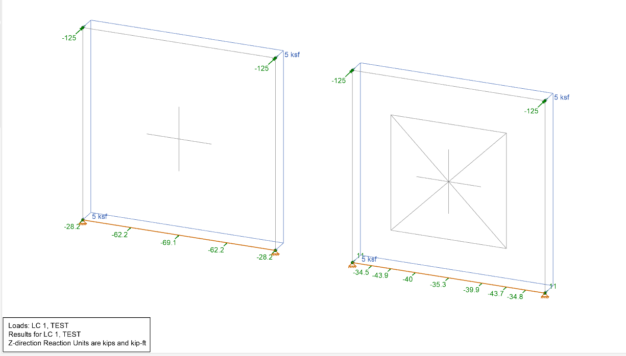
When designing shear walls in RISA-3D, it’s common to add surface...
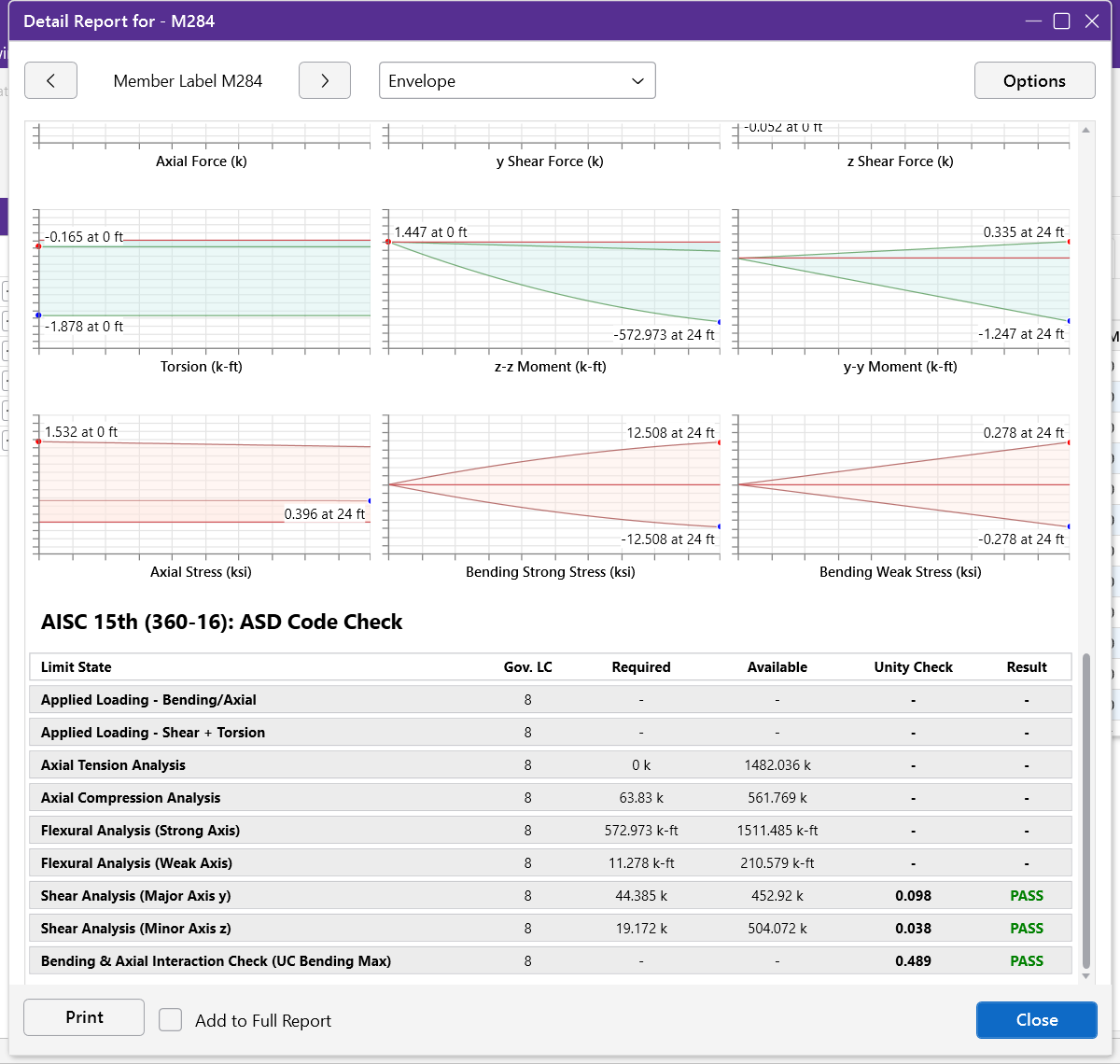
When the Graphs Don’t Match: Understanding the Controlling Case A common...