


 By: RISA
How to Model Trusses in RISAFloor
In RISAFloor on the roof level, you layout only the top chords of the...
Key Highlights
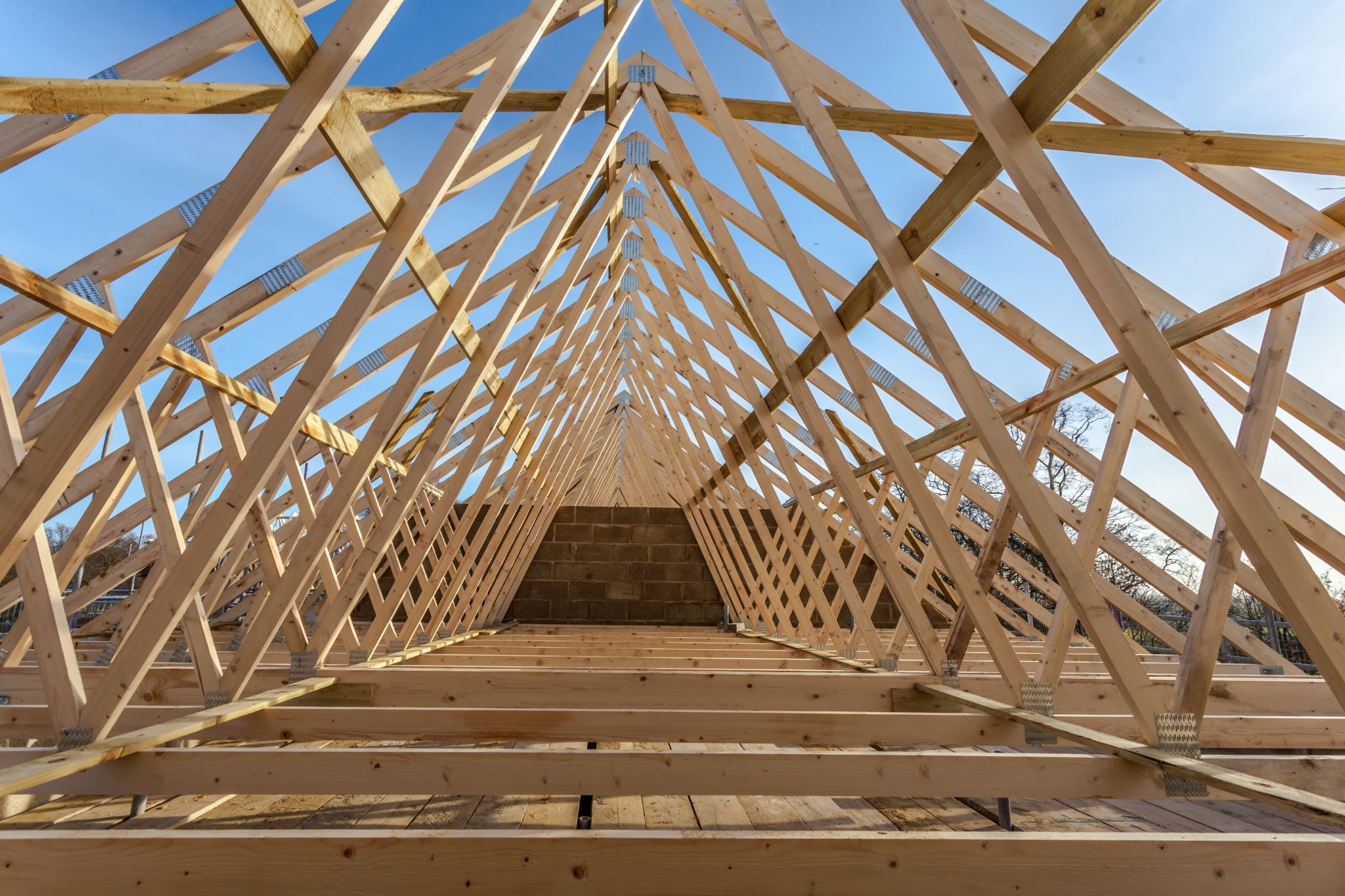
In structural engineering, a truss is a framework composed of members connected at joints to form a rigid structure, typically characterized by a triangulated system. The primary purpose of a truss is to bridge long spans while supporting heavy loads with minimal material.
In this article, we’ll cover the basics of what a truss is, as well as talk about the most common types used in construction today.
To understand how a truss functions, you must first speak the language. A standard truss is comprised of several distinct parts:
Choosing the right truss depends on the span, the loading conditions (snow, wind, or traffic), and the desired aesthetic. Here are the industry-standard configurations.
The Pratt truss is designed so that the diagonals are in tension and the shorter vertical members handle the compression. Because steel is excellent at resisting tension even in thin sections, this layout allows for a very lightweight, material-efficient design. It is the go-to truss configuration for horizontal spans where gravity is the primary force.
Typical Applications: Long-span bridges, industrial floor systems, and commercial roof spans.

The Warren truss distributes loads through a repeating series of equilateral or isosceles triangles. It often functions without vertical members, meaning the diagonals take turns handling both tension and compression. This simplicity makes it one of the easiest trusses to manufacture and assemble in a fabrication shop.
Typical Applications: Steel railroad bridges, simple roof structures, and open-web steel joists.

Think of the Howe as the "inverse" of the Pratt. In this configuration, the diagonals are in compression. While this makes steel members prone to buckling, it is perfect for heavy timber. Since wood has excellent natural compressive strength, the Howe allows for thick timber diagonals to handle compression while slim steel rods carry the vertical tension forces.
Typical Applications: Heavy timber roof systems, historic wood bridges, and decorative lodge framing.

The Scissor truss is unique because its bottom chord is inclined rather than flat. This behavior allows it to support the roof load while creating a vaulted "cathedral" interior. However, because of the angled bottom chord, it exerts a lateral "thrust" or outward push on the supporting walls, which must be accounted for in the overall building design.
Typical Applications: Churches, vaulted residential living rooms, and high-end commercial showrooms.
While the theory of a truss relies on simple triangles, real-world engineering requires a deep dive into how these members behave under stress. To move from a conceptual sketch to a buildable design, engineers must account for several physical realities:
In a truss, half the members are typically in compression. These members can fail by "buckling" (bowing sideways) long before the material actually crushes. Engineers must calculate the slenderness ratio of every compression member and strategically add lateral bracing to reduce their "unbraced length."
Forces in a truss are not static. During a high-wind event, the pressure inside a building can create an "uplift" force that exceeds the weight of the roof. This can cause a member that is usually in tension to suddenly snap into compression. Designers must size every chord and web to handle these load reversals so the structure remains stable during storms or seismic activity.
A truss is incredibly strong in its own plane, but it is effectively a "house of cards" in the lateral direction. Without a comprehensive system of perpendicular bracing and bridging, the entire row of trusses can topple sideways. Bracing is a structural requirement to prevent out-of-plane buckling.
Choosing to implement a truss system over a traditional solid beam is rarely a snap decision. While trusses offer unparalleled efficiency, they also introduce specific spatial and maintenance considerations that a firm or structural engineer must weigh early in the design phase.
From a structural and economic standpoint, trusses are often the "hero" of the job site. Their primary appeal lies in their exceptional strength-to-weight ratio. In practical terms, this means you can span 60 feet or more with a wood truss that two crew members could manually maneuver into place, a feat that would be physically impossible and prohibitively expensive with a solid timber or steel I-beam.
From a project management perspective, the speed of construction is a major differentiator. Most trusses are prefabricated in a controlled fabrication shop and delivered to the site ready to be "swung" into place by a crane. This modularity minimizes on-site errors and slashes labor hours. Once installed, the "open-web" nature of the truss offers a hidden perk: seamless integration of services.
Of course, trusses aren't a "magic bullet" for every application. The most significant hurdle is often spatial requirements. To achieve those impressive spans, a truss requires "depth" (the distance between the top and bottom chords). While a solid steel plate might be thin, a truss needs vertical room to allow its geometry to work. If you are designing a building with strict height clearances, a truss might take up more "vertical real estate" than your floor-to-floor height allows.
There is also the matter of design complexity. While a simple beam can often be sized using a span table, a truss is a complex system of interconnected members. Designing these by hand to account for various load combinations (like uneven snow loads or high wind gusts) is incredibly tedious and prone to human error. This is why modern structural engineers rely so heavily on sophisticated FEA software to ensure every node and chord is optimized.
If your model assumes a member is braced every 2 feet, but the actual construction only braces it every 8 feet, the software will drastically overstate the member's buckling capacity. Engineers must ensure the "unbraced length" in the software matches the physical reality of the framing.
Forgetting to include asymmetrical snow loads (where snow drifts on only one side of the ridge) or lateral wind loads can leave a truss vulnerable. A truss that passes under a uniform load might fail when the forces are concentrated on a single sub-triangle.
It’s easy to focus on an individual truss and forget how it connects to the rest of the building. If the supports (walls or columns) aren't stiff enough to resist the "thrust" or lateral movement of the truss, the entire system can become unstable.
If you are moving from theory to execution, these walkthroughs demonstrate the workflow for designing high-performance trusses:
Are you ready to optimize your next truss project? Start a 10-Day Free Trial to test drive the full RISA product suite and automate your layout process in minutes.
In RISAFloor on the roof level, you layout only the top chords of the...
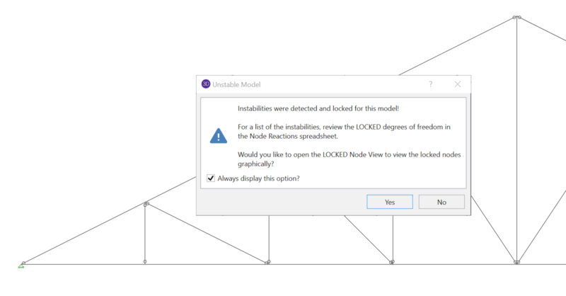
When running a truss model in RISA-3D or RISA-2D, it’s quite common to...
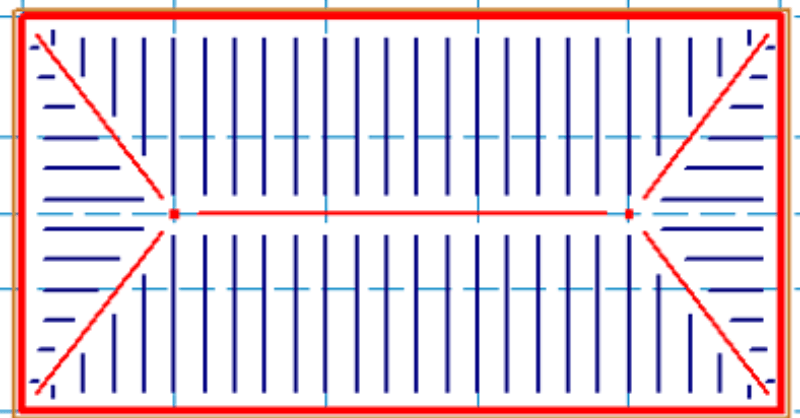
Using this method in RISAFloor, we are not actually designing the...