How to Model Trusses in RISAFloor
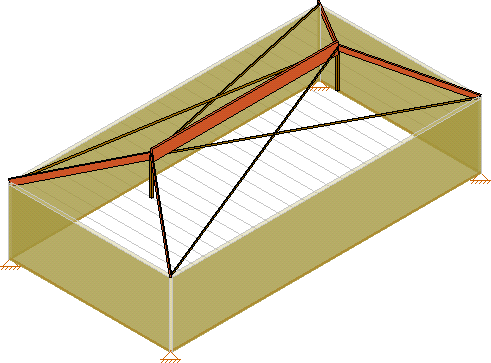
In RISAFloor on the roof level, you layout only the top chords of the...
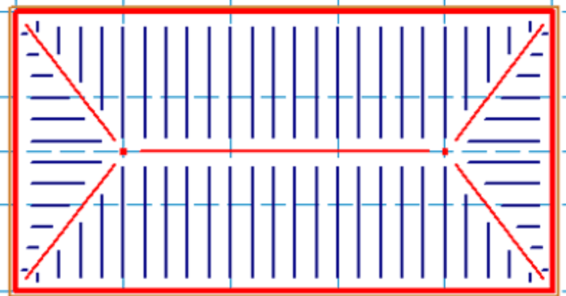
Using this method in RISAFloor, we are not actually designing the trusses, but just adding “dummy” bottom and top chords to correctly calculate the loading and help distribute the loads to the walls.
In RISAFloor, you need two floors in order to draw the bottom chord and top chords. The second floor can be a little bit higher than the first floor; 6 inches is reasonable for the heel height of the truss.

Floor Plan 1: Model the bottom chord of the trusses. Define these members as lateral members so that we bring them into RISA-3D. Make sure to add a Diaphragm Region on this level in order to distribute the loads only to the walls.
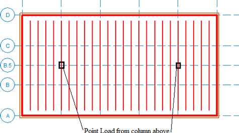
Floor Plan 2: This level is sloped and the wind loads are generated based on this slope. Make sure to turn on the Generate Roof Wind Loads in the Wind Loads dialogue. The top chords are modeled as gravity and the ridge beams outline the slope as lateral members. The gravity columns will point load Floor Plan 1 (shown above), and carry the loads to the walls.
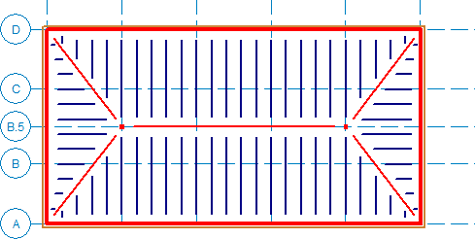
Take the model into RISA-3D, and the wind loads will be applied to the sloping members as well as the wall elements. Using Flexible Diaphragms distributes the loads to the members directly.
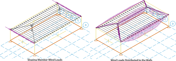
You also may consider adding a smaller member as cross bracing on the sloped portion of your model to simulate the stiffness of the decking. Make sure to call it a H-Brace so that it doesn’t get any loads attributed to it.

In RISAFloor on the roof level, you layout only the top chords of the...

RISAFloor, RISA-3D, and RISAFoundation all allow the user to export a...
Integrating structural models from RISA to Revit seamlessly can...