Basic Description
Pattern based skip loading has recently been added into RISAFloor beam design. This can be turned on or off using the checkbox in the Solution tab of the (Global) Model Settings shown below.
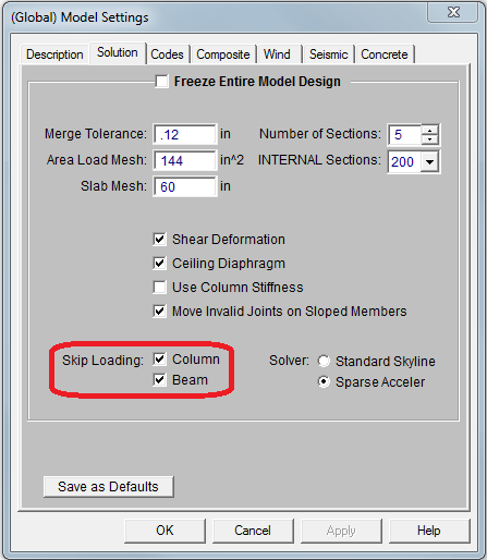
This new feature applies to continuous beams that span over multiple supports. The various types of live loading will be included or excluded per span in various patterns in an effort to produce the worst case shear, moment and reactions.
This complies with the “Partial Loading” requirements of ASCE 7-10/16 Section 4.3.3.
Load Patterns Utilized
The various live load patterns used for skip loading are shown in the images / patterns shown below.
-
Pattern A: Full Load on Beam

-
Pattern B: Intended to produce the maximum positive moments for center span (and every other odd span)

-
Pattern C: Intended to produce the maximum negative moment for cantilevers and/or maximum positive moment on the off-center span beams (and ever other even span beam).

-
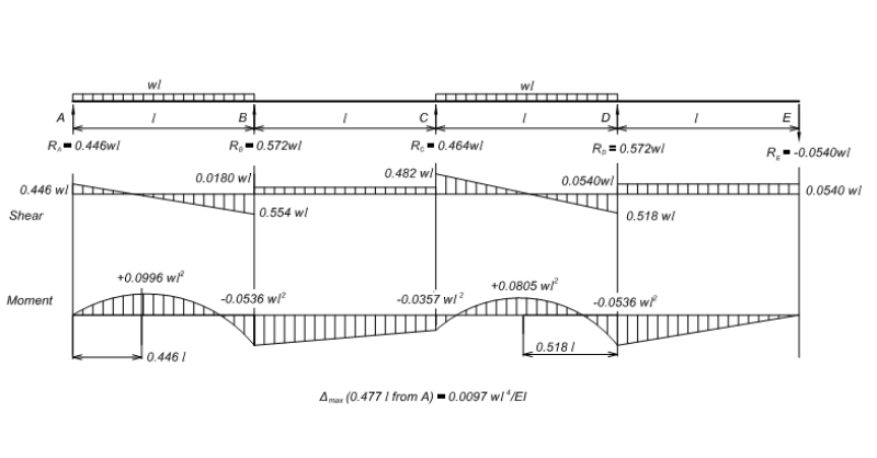
Pattern D: Two adjacent bays loaded with one bay skipped in between. This is intended to produce the maximum reaction for the first interior supports.

-
Pattern E: Two adjacent bays loaded with one bay skipped in between. This is intended to produce the maximum reaction for the supports that don’t get covered by pattern d.

Controlling the Load Diagrams in the Detail Report
When viewing the detail report for a beam that is subject to skip loading, the report may be manipulated to show you exactly what loading was used for each “Load Pattern”. This is only available when viewing a live load category where skip loading is applicable (Live Load, Live Load Special, Roof Live Load, Snow Load, and Rain Load). It is NOT available for the display of Load Combinations, only Load Categories.
Merely click on the Patterns drop down menu to change which load patterns get displayed.

This drop down menu will affect the displayed load, shear, moment and deflection diagrams. It does NOT affect the summary code checks which are based on all the various load cases.
The displayed loads, shears, moments and deflections will update based on the pattern selected.
Detail Report Summary
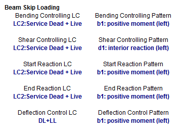
The member detail report has a summary for beam identifying which pattern controlled the calculations of the reported beam results. This includes the bending check, the shear check, the deflection check and the maximum reactions at the starting and ending supports for the beam.
Analysis
Multi-span beams are included in the analysis of the overall floor solution with their full loading (case a). However, for their individual design results, the program uses a separate internal beam solver to automatically check the various load patterns which may produce a maximum moment, shear or reaction for the beam.
In the images shown in this article, the supports are shown as pinned. This is to represent a rigid vertical column support with no rotational stiffness. In the actual analysis, supports are viewed as springs based on actual column or girder stiffness.


