


 By: Admin
Analysis Offsets now Available
RISA-3D v15 includes "analysis offsets" which moves the centroid of the...
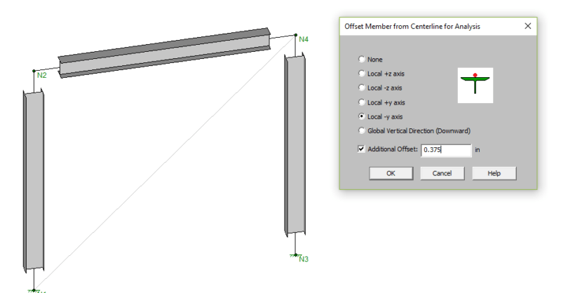
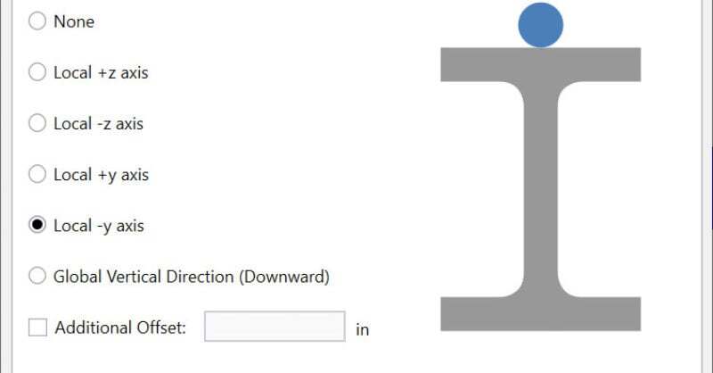
In a previous article we discussed how the Analysis Offsets feature in RISA-3D works and how it can be used to model members at top of steel. In this article, we will discuss some specific situations and how the results change with the analysis offset set as top of member (local -y axis).
In most cases setting the analysis offset to top of member should be used with caution since it can lead to odd and unexpected behavior within the model. While using analysis offsets may make the rendered view of your model look more realistic, your analysis model will get unnecessarily complicated.
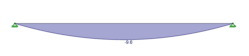
To start, let’s look at a simply supported beam example and compare the bending moment with and without the analysis offset.
Moment diagram with the Analysis Offset set to None:
Moment diagram with the Analysis Offset set to Local -y axis (top of member):
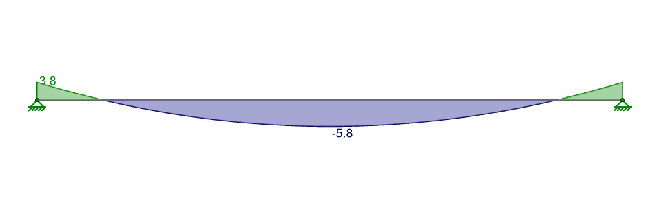
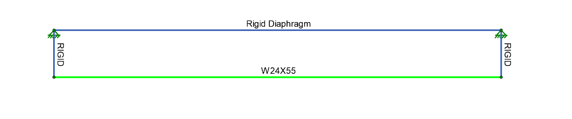
When comparing the results, it appears that we have a fixed-fixed beam rather than a pin-pin beam. What is happening can be shown by modeling this situation as RISA does internally, adding rigid links and dropping the member down by half its depth (11.95”).
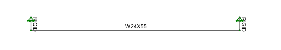
The rigid link members are modeled with fixed-fixed end releases and combining this with the fixed-fixed end releases on the beam creates a rigid connection that induces moment at the beam end. A solution to this specific issue is to create fixed-fixed boundary conditions and then pin-pin end releases on the beam. When we do this we then have releases on the beam ends that do not induce moment.
These simple cases easily showcase how RISA-3D treats the analysis offset when top of member is desire. However, in a more complex structure, the difference in strong axis moment between a centerline alignment and a top of member alignment will be very small (see the image below).
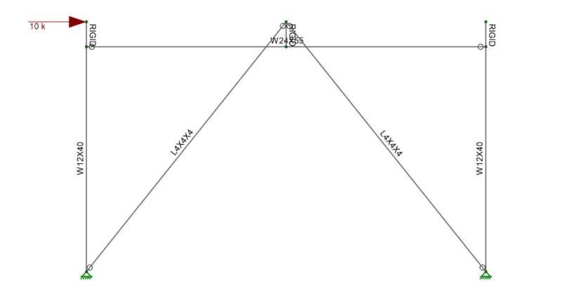
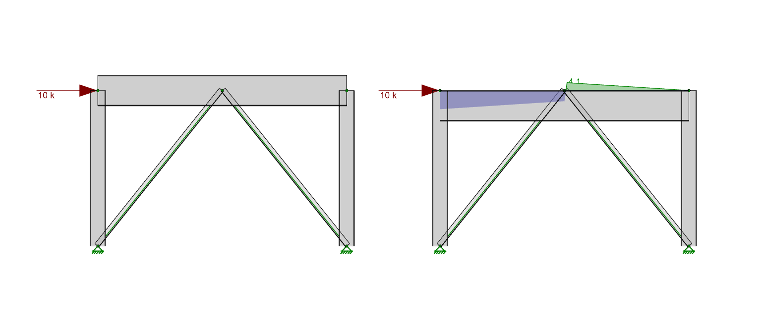
While most building floor framing utilizes members at top of steel, analyzing the members in this fashion can cause odd results because of the presence of a rigid or semi-rigid diaphragm in the same plane. Let’s look at the case of a chevron brace frame with a lateral load.
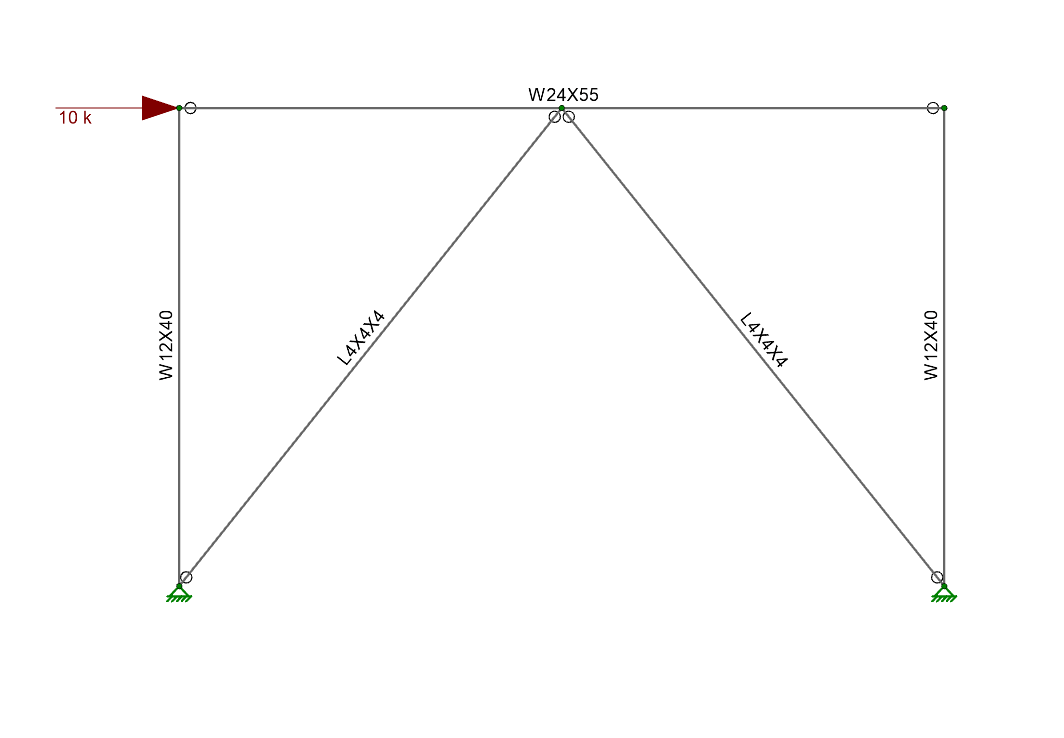
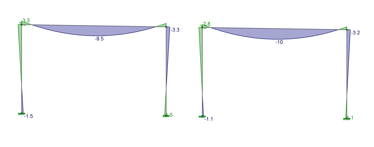
If we change the analysis offset of the beam to top of member (Local -y axis) and compare results, we first see that the axial forces are generally very similar. However, if we look at the strong axis bending moment a large moment shows up in the beam that is likely not realistic.
Internally again, rigid links are being created causing eccentricities that are inducing these moments.
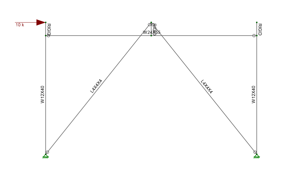
Similar problems can occur with a rigid diaphragm (where all nodes at the diaphragm are connected with rigid links) in the same plane as a member with the analysis offset set to local -y axis.
Ultimately, using analysis offsets in order to evaluate beams at top of member can add significant complexity to the model, while also creating results that may be unrealistic for a building structure that utilizes a rigid or semi-rigid diaphragm. As a result, this feature should be used carefully.
RISA-3D v15 includes "analysis offsets" which moves the centroid of the...
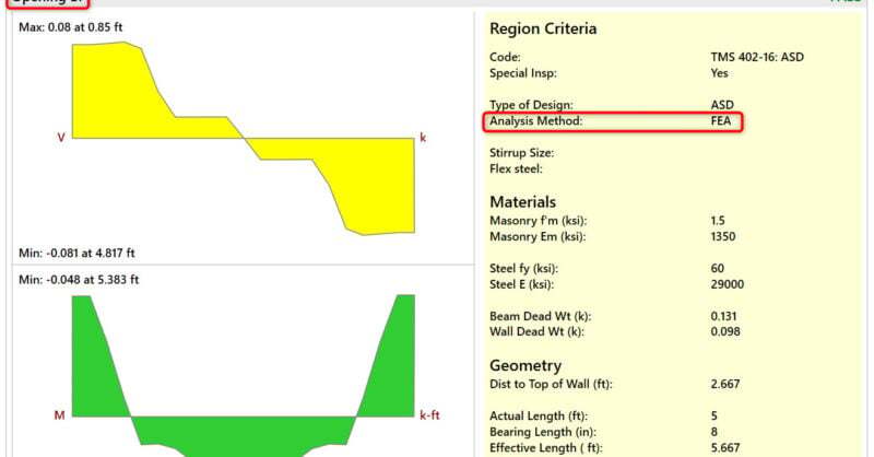
In RISA-3D, the current method of design for masonry lintels is Simply...
Have you ever wondered what the Analysis Offset feature does? Let’s...