


 By: RISA
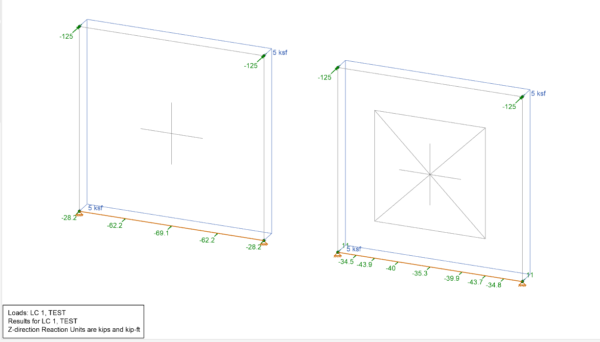
How RISA-3D Handles Wall Surface Loads at Openings
When designing shear walls in RISA-3D, it’s common to add surface...
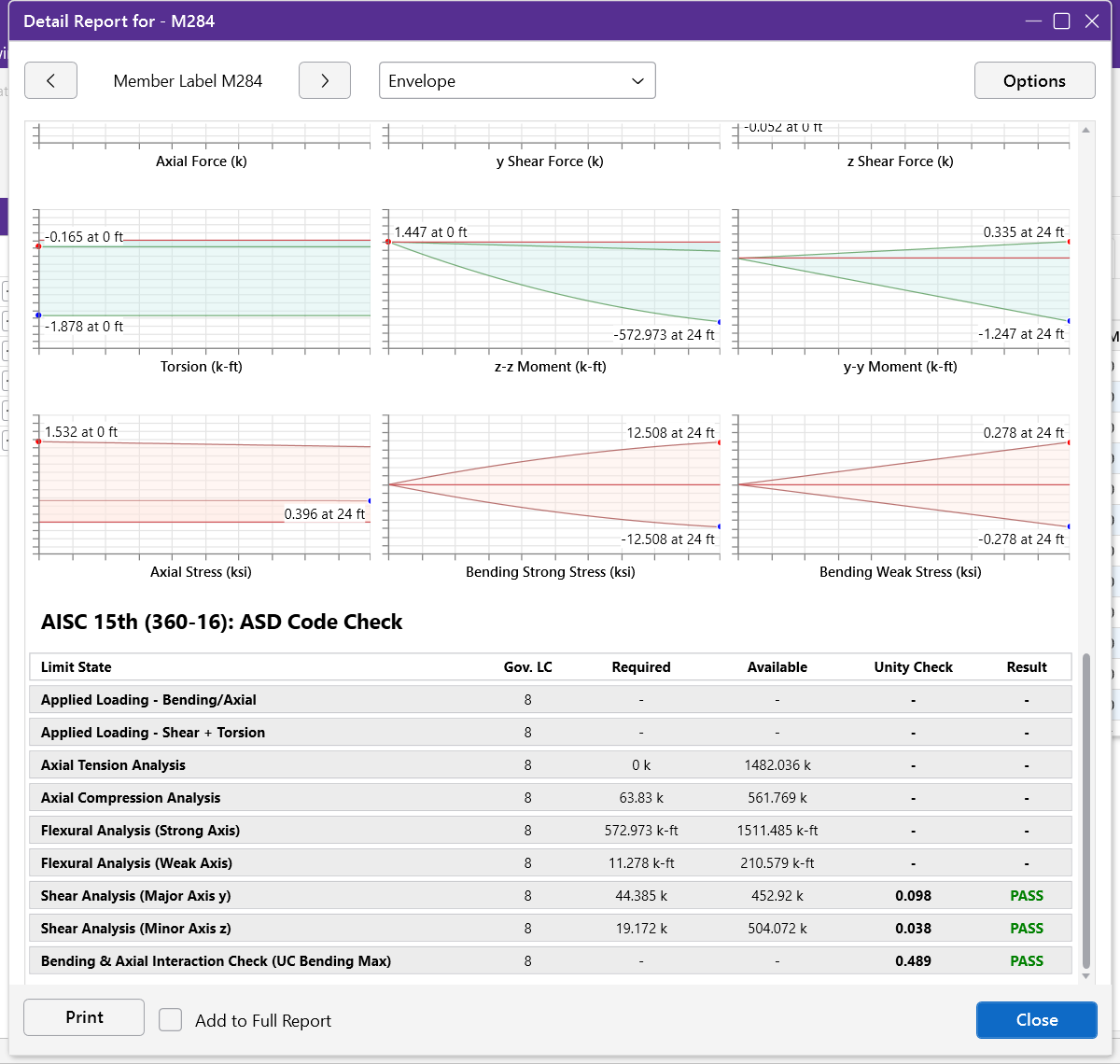
A common question from users is why the maximum moment shown in the Detail Report graphs doesn’t match the required flexural moment reported in the design results. At first glance, this difference can be confusing — but it comes down to how RISA determines the controlling condition for design.


Each member design is based on the governing load combination and the controlling location along the member where the combined effects of bending and axial forces produce the highest demand-to-capacity ratio (DCR). The graphs, on the other hand, show the pure bending moment diagram, which does not include these combined effects.
To fully understand the calculation behind the flexural demand (and shear), expand the Applied Loading section of the Detail Report. There you’ll see how RISA combines:
Bending + Axial forces for flexural checks

Shear + Torsion forces for shear checks

By reviewing both the governing load combination (Gov LC) and the location of the controlling results within the expanded sections, you can pinpoint exactly where and why your member design is governed by interaction effects rather than just the maximum moment value from the diagram.
For members experiencing torsion, there’s an additional layer to consider. RISA incorporates warping stresses into the combined stress state — meaning the total design demand is a combination of bending, axial, shear, and torsional effects.
However, it’s important to note RISA’s limitations regarding torsion on warping members. RISA currently considers only Case 2 from AISC Design Guide 9, which represents torsion due to racking of the structure. Torsion considerations for any other cases can be over- or underestimated, as RISA’s calculation of torsion capacity is not intended for point or line torques applied to individual members.
For more information on torsional modeling and limitations, see Online Help Documentation.
The difference between the moment graph and the required flexural demand isn’t a flaw — it’s a reflection of how RISA-3D accurately combines multiple force effects to determine the true controlling condition for design.
When reviewing results, use the Applied Loading sections to see the full interaction of bending, axial, shear, and torsional effects. Doing so provides a complete, code-based view of how your structure performs under load — exactly as intended.
When designing shear walls in RISA-3D, it’s common to add surface...
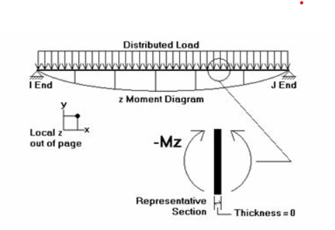
RISA software products use different sign conventions depending on the...
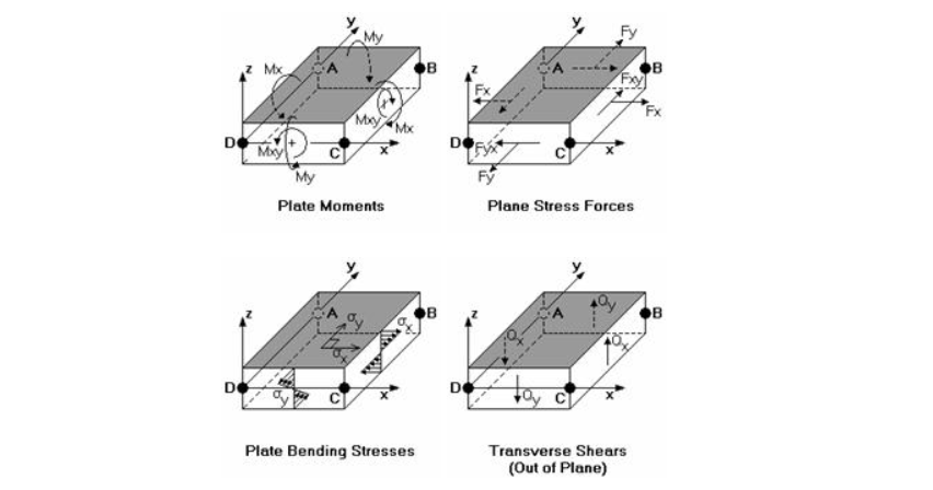
While members (beams and columns) follow conventions tied to their local...