


 By: RISA
Nesting Load Combinations
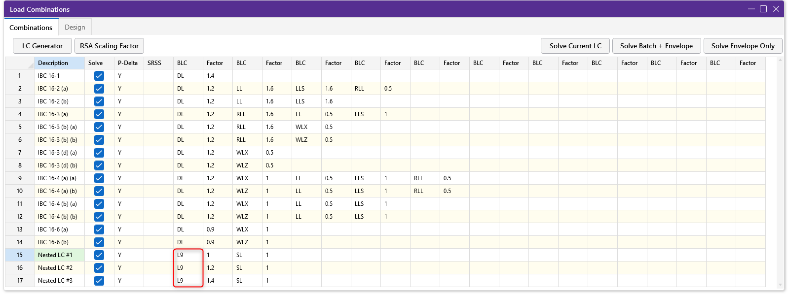
The Load Combinations spreadsheet in RISA-3D is limited to ten columns...
When defining loads in RISA, you’ll see two live load categories: LL and LLS. Both are live loads, but the preset load combinations incorporate them differently. Understanding this difference helps you assign loads correctly and get accurate results.
The two categories exist to incorporate the different load factors required for the live load as prescribed in both ASCE 7 and NBC.
In ASCE 7, an exception is allowed for the load factor applied to the live load in strength design (LRFD) load combinations.
“The load factor on L in combinations 3a and 4a is permitted to equal 0.5 for all occupancies in which L0 in Chapter 4, Table 4.3-1, is less than or equal to 100psf (4.78 kN/m2), with the exception of garages or areas occupied as places of public assembly.”
ASCE 7-22, Section 2.3.1
“The load factor on L in combination 6 is permitted to equal 0.5 for all occupancies in which L0 in Chapter 4, Table 4.3-1, is less than or equal to 100psf (4.78 kN/m2), with the exception of garages or areas occupied as places of public assembly.”
ASCE 7-22, Section 2.3.6
NBC calls for an increase to the live load for specific areas in both ultimate and service load combinations.
“The companion-load factor for live loads L in Table 4.1.3.2-A and LXC in Table 4.1.3.2.-B shall be increased by 0.5 for storage areas, and equipment areas and service rooms referred to in Table 4.1.5.3.
NBC 2020, Clause 4.1.3.2.(7)
“The companion load factor of 0.35 for live load, L, shall be increased to 0.5 for storage areas, equipment arrests and service rooms.”
NBC 2020, Table 4.1.3.4., Note (2)
By providing two load categories, the live load is able to be easily categorized and assigned with the correct factor.
When using the Load Combination Generator, RISA automatically incorporates both LL and LLS anywhere live load appears in the code prescribed load combinations.
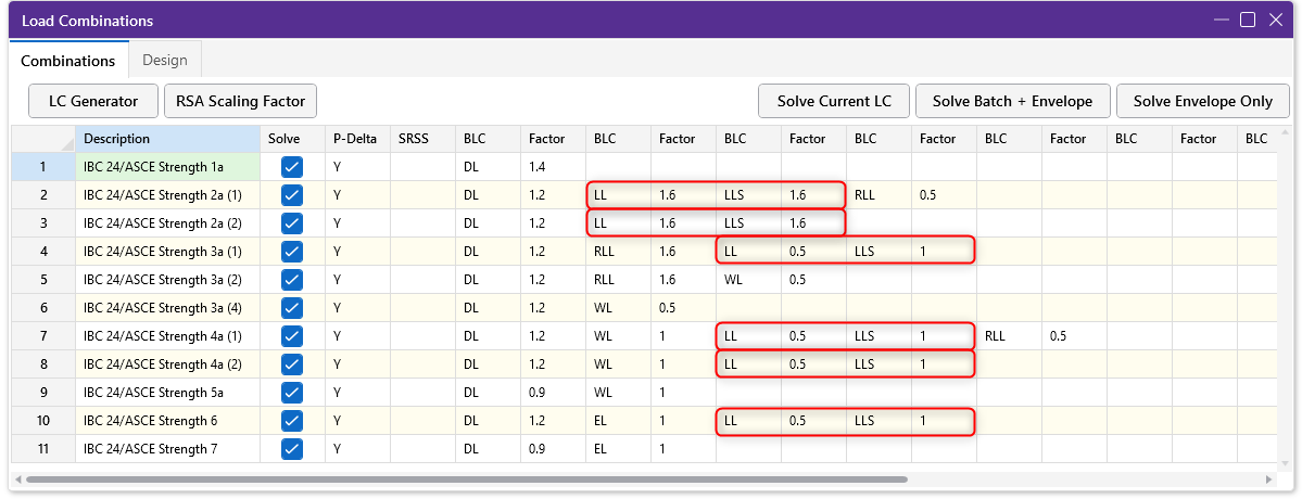
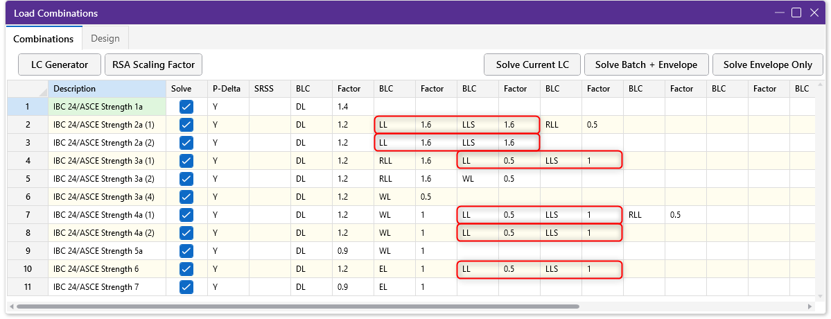
The key difference is when using strength design (LRFD). ASCE 7 includes the exception noted above for combinations 3a, 4a, and 6.
RISA applies the 0.5 factor permitted in this exception to the LL category. LLS is a special live load category that does not qualify for this exception and keeps the 1.0 factor applied. Both load categories will be in the generated LRFD load combinations but with different factors applied.
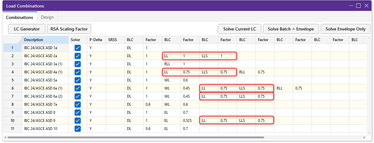
For allowable stress design (ASD) load combinations, ASCE 7 does not provide an exception based on the type of the live load. As a result, LL and LLS will receive the same factor in ASD combinations when using the Load Combination Generator.
Similar to when you're using the United States codes, RISA automatically incorporates both LL and LLS anywhere live load appears in the code prescribed load combinations when using the Load Combination Generator.
The key difference is when the live load is classified as a companion load per the code section above. We see this classification for the ultimate limit state design in load combinations 3, 4, and 5. RISA applies the standard 0.5 factor listed in the load combinations to the LL category. The LLS category will receive the 0.5 increase noted in Clause 4.1.3.2.(7) for specific live loads as quoted above.
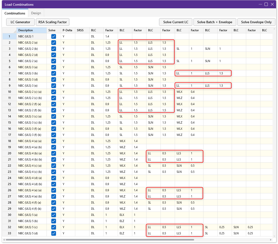
For service level design, load combinations 2 and 3 list live load as a companion load. These combinations specify the load factor increase from 0.35 to 0.5 depending on the type of live load. Again, this increase is reflected in the generated load combinations with the LL category receiving the standard factor and the LLS category receiving the increased load factor.
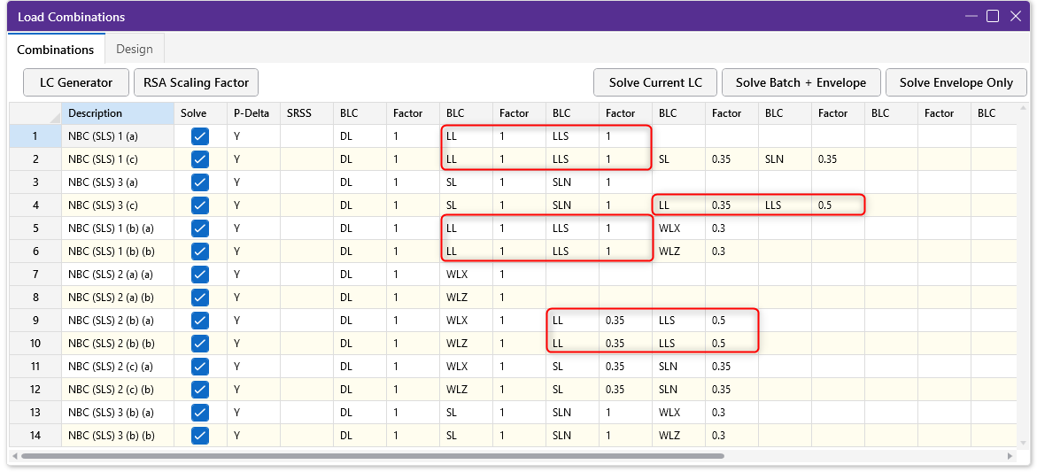
The main deciding factor for which load category to use should be whether the live load qualifies for the smaller load factor defined in the code.
If you’re either entering your own custom load combinations or using ASD combinations for your design, then the LL versus LLS distinction is not critical for an accurate design. It will only affect your design if you assign different factors to the different categories.
It can be best practice to follow the same guidelines as outlined here when assigning live load in your model even if you're not planning to use the LRFD or Canadian load combination generator. This will provide consistency across models and creates a safeguard against errors if you need to add strength design to your model later in the process.

The Load Combinations spreadsheet in RISA-3D is limited to ten columns...
V-Brace frames in RISA-3D seismic design have unbalanced forces shown...
The consideration of Live Load reduction is a feature that has been in...