


Accidental Torsion for Semi-Rigid Diaphragms in RISAFloor
The latest releases of RISAFloor (Version 15.0.1) and RISA-3D (Version...
It is important to understand how RISA is modeling your load distributions when applying flexible diaphragms. The flexible diaphragm distributes loads based on tributary area, but RISA breaks up the areas based on the nearest support elements on either side. When RISA sees support elements on both sides, the load is split (or distributed) to both element sides. However if one side is missing a support element, then all that load will be attributed to the one side resulting in one-way distribution.
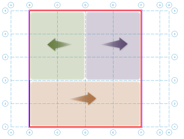
Let’s see this in a simple example shown below. Consider a rectangular building with lateral load applied in the North-South direction (plan up/down), and resisting shear walls along grids “B” and “F”. However, the shear wall along grid “B” has a shorter length extending between gridlines “3” and “5” only. In this case, only the tributary load area highlighted in green becomes assigned to the left shear wall. The rest of the load area highlighted in purple and orange is assigned to the right shear wall.
Alternative Methods: If the program’s load distribution method does not work for our engineering situation, please review these two alternative modeling suggestions. These are just suggestions and will need to be reviewed using your engineering judgment for your engineering situation.
One way to work around the program’s tributary area distribution is to model some type of drag strut or collector. In our above example, you could model a collector along grid line “B” between gridlines “1” and “3”.
If you need full manual control of the load distribution, run the load generator with the code set to "none" in order to clear the generated loads, then you can manually enter lateral loads as needed.
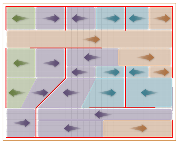
To see how the program recognizes flexible diaphragm tributary areas in a more complex lateral system, let’s consider another example shown below. Considering how a North-South direction lateral load (plan up/down) will be distributed to the lateral system shown in the image below. Lateral shear walls are shown in red with a few gravity beams shown in blue. Again for each area section, the program is looking for the nearest support element. Tributary areas that belong to each shear wall are color coded with arrows indicating which wall that area belongs to. Also notice how the diagonal wall is handled. Users may need to consider these effects if they have diagonal walls or walls that aren't aligned with the global X or Z axis.
For more information on diaphragms, see our other articles.
The latest releases of RISAFloor (Version 15.0.1) and RISA-3D (Version...
RISAFloor supports the use of flexible diaphragms on both flat and...
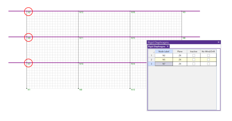
In RISA-3D, rigid diaphragms can be added using the Diaphragm...