How to Check Frame Story Shears in RISA-3D
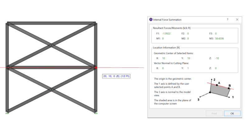
When using rigid diaphragm analysis in RISA-3D it can be useful to...
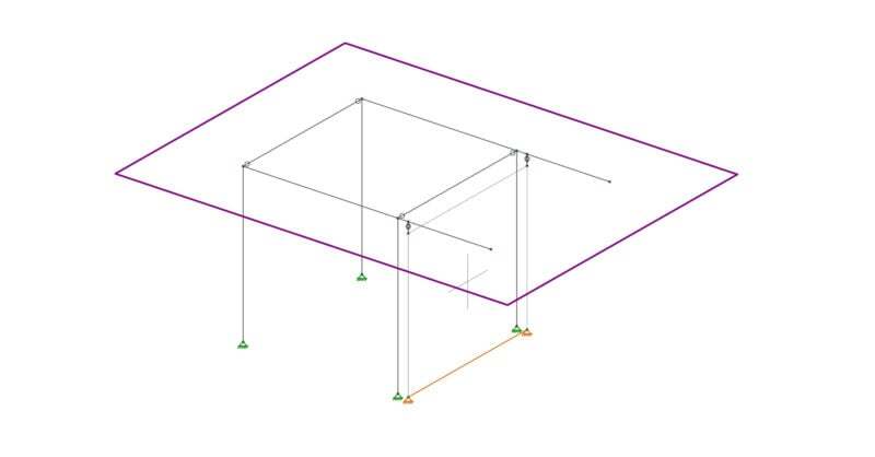
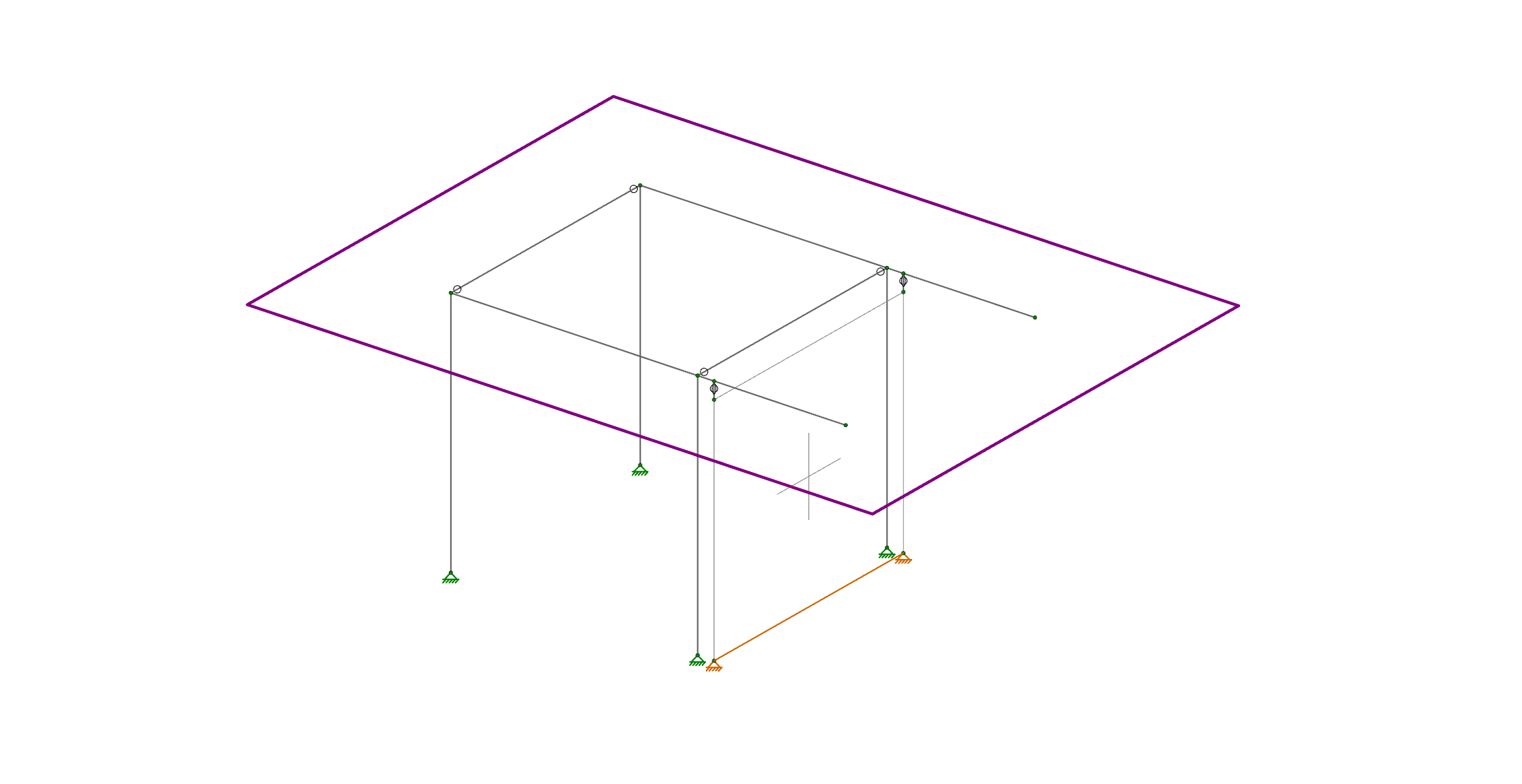
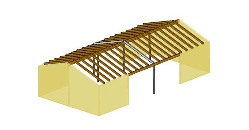
Let’s consider the example of the frame shown below. Suppose there is a diaphragm present at the framing level, and that the wall shown is intended only to handle the lateral loads. In reality the columns will be in-line with the wall, and the cantilever beams will pass over the wall without bearing on it.
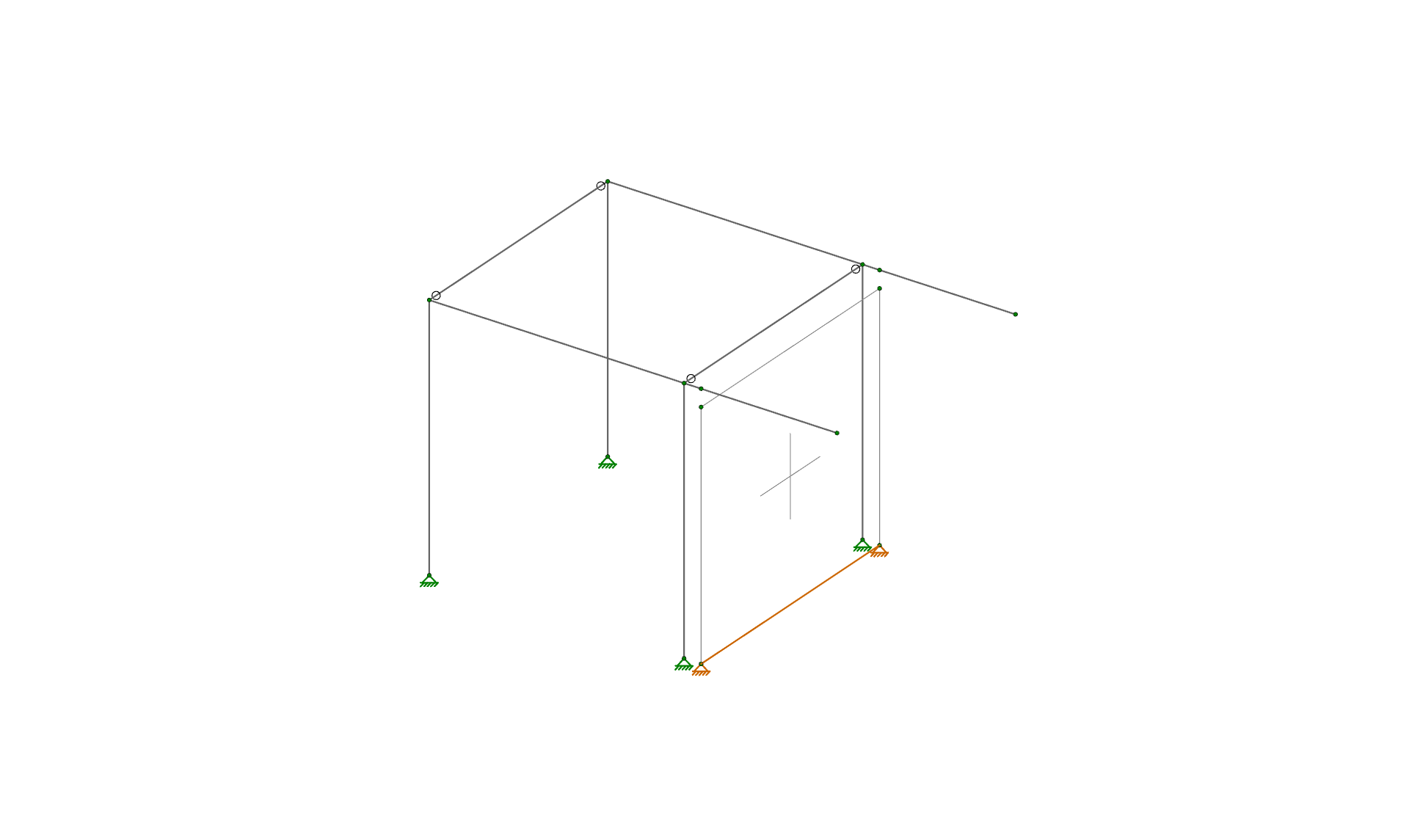
In order to prevent the columns from sharing axial force with the wall they must not touch the wall. Therefore the wall should be modeled in RISA-3D as not touching the columns, in this case by moving it outwards a couple inches. In order to prevent the cantilevers from bearing on the wall they also must not touch the wall.
Therefore the wall is modeled as a few inches short of the beams. This would be fine, except for the fact that the wall will no longer be connected to the diaphragm at the framing level. For this we must use rigid links. Draw rigid links vertically from the top of the wall to the cantilever beam as shown below:
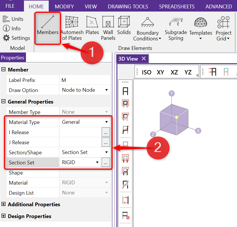
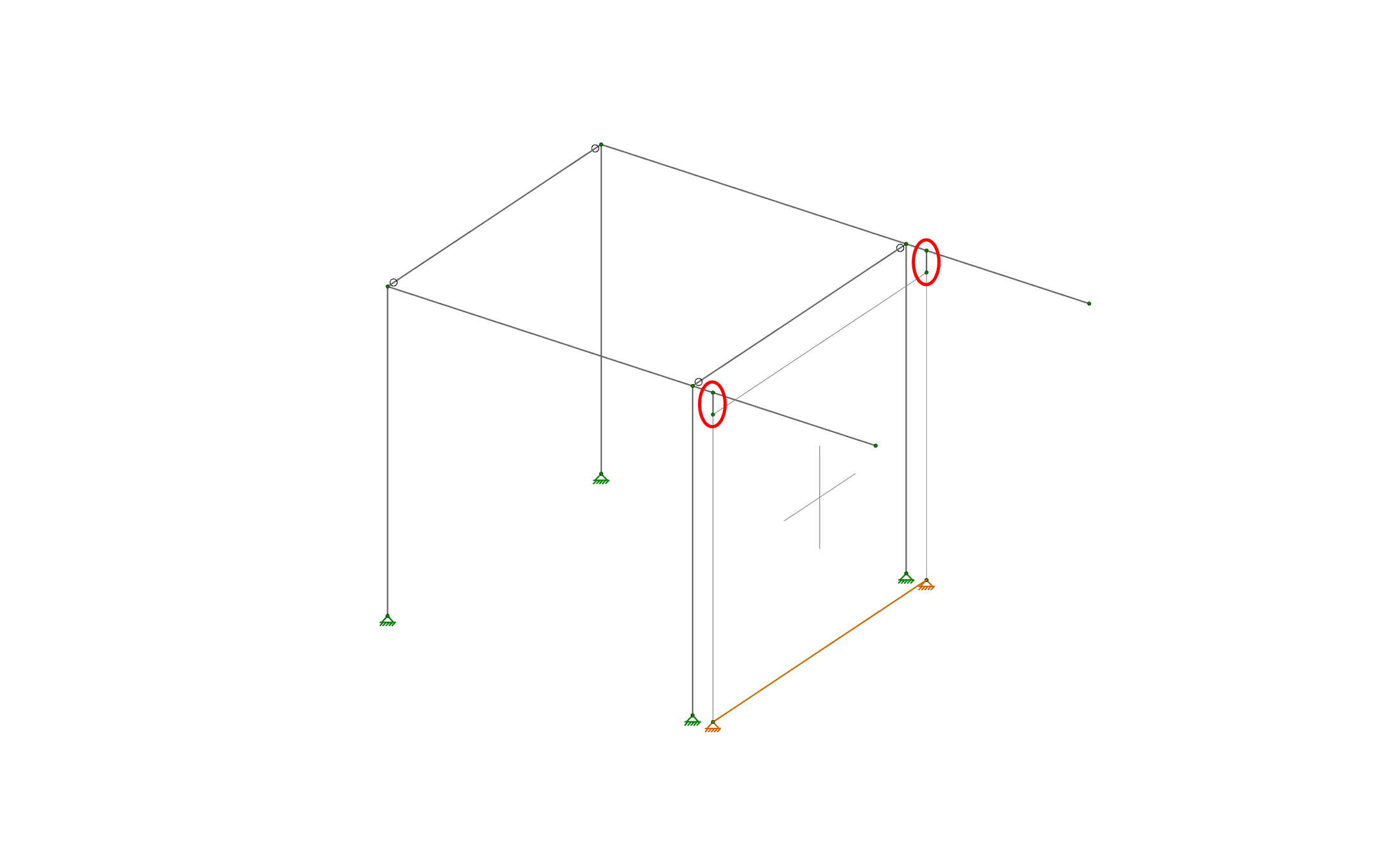
By setting the rigid links to be fully fixed at both ends we have defeated the purpose of dropping the wall, since now the beams will still bear on top of the wall. We need to adjust the member end releases for the rigid links to control what forces they transfer to the wall. First, turn on the display of member local axes:
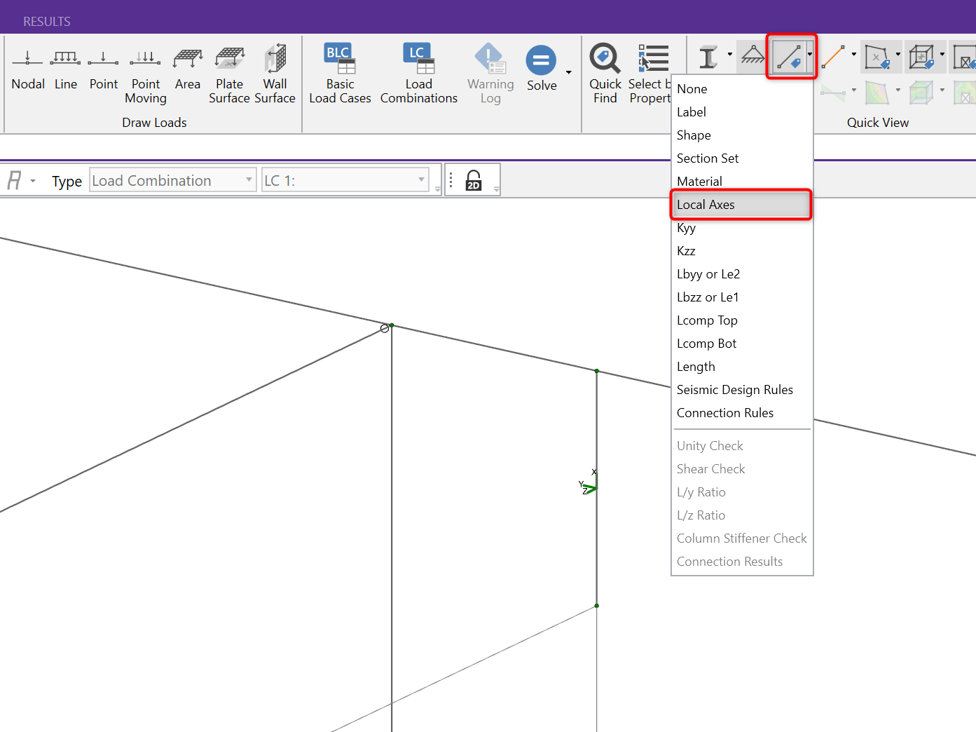
Next, double click on each rigid link and set its member end releases. In this example the J-End is the top, which is where we want to release the link for axial forces, as well as all moments (we only want it to transfer shear to the wall).
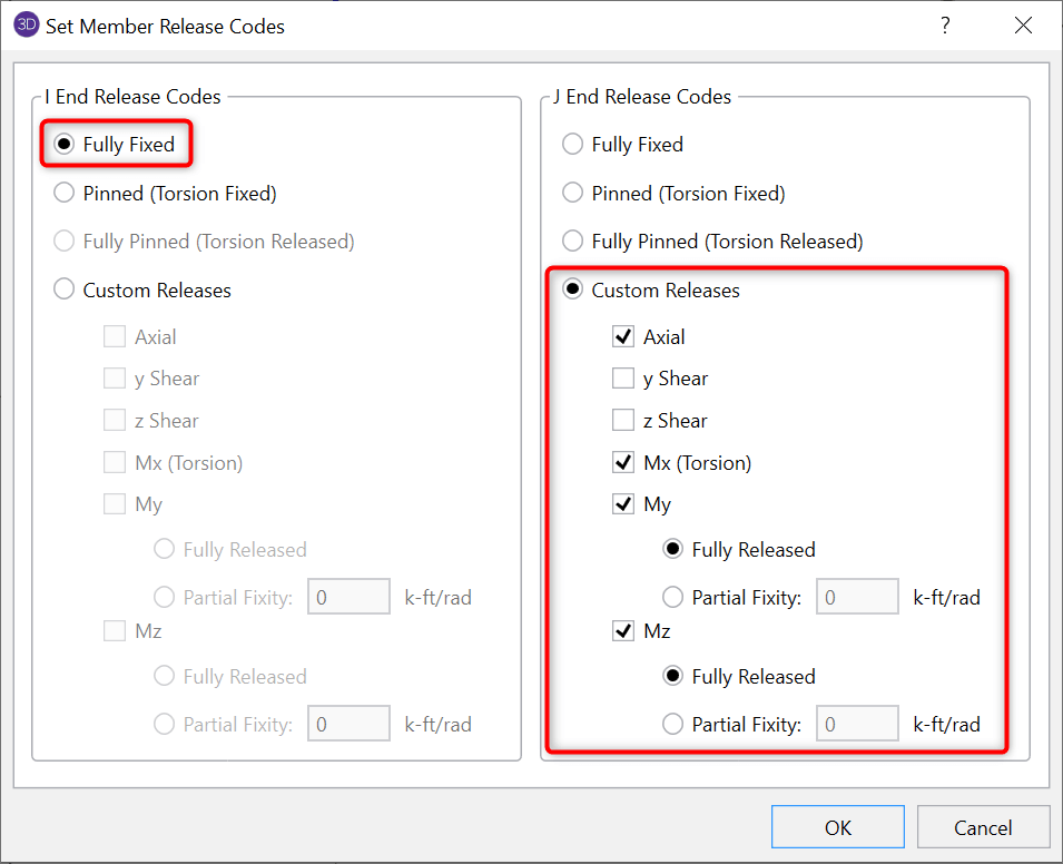
The pin symbol shown at the top of each rigid link confirms that the special end releases have been applied. The wall will now take no gravity loads from the frame, but it will participate to carry shear from the diaphragm shown in purple below.
When using rigid diaphragm analysis in RISA-3D it can be useful to...
RISAFloor supports the use of flexible diaphragms on both flat and...
With the release of RISA-3D v19.0.2, you can now design special...