


 By: RISA

Beam Deflection Ratio Options
RISA-3D v16.0.4 introduces an enhancement that will allow for more...
There are many different types deflection values calculated by RISA-3D. Let’s take a deeper dive into each.
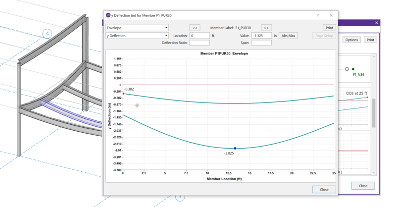
Absolute deflection is the maximum absolute value for deflection in the member local lateral y- and z-axis. In engineering terms, this value is also commonly referred to as global deflection since it encompasses the entire movement of a member as the entire model moves. The term “global deflection” is not used in RISA-3D since this can be confusing when also talking about global and local axis for direction. The values for absolute deflection are reported in the Service and Strength tabs of the Member Deflections spreadsheet.
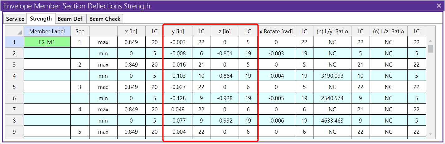
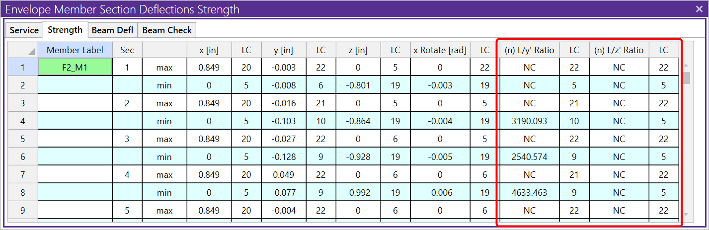
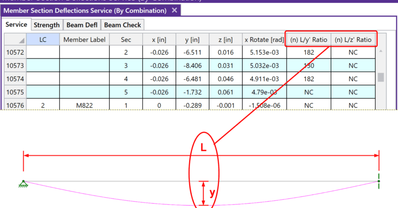
The deflection value used in the member deflection ratios L/y’ and L/z’ is the relative deflection: y’ and z’. This is the deflection of a member relative to its own non-deflected shape. This deflection only captures the effects of loading specific to the member itself and does not include any effects from a neighboring member’s deflection. The deflection ratios L/y’ and L/z’ are applicable to all member types (beams, columns, and braces). It is important to understand that the relative deflection used in this ratio is not equal to the absolute deflection that is reported in the columns to the left.
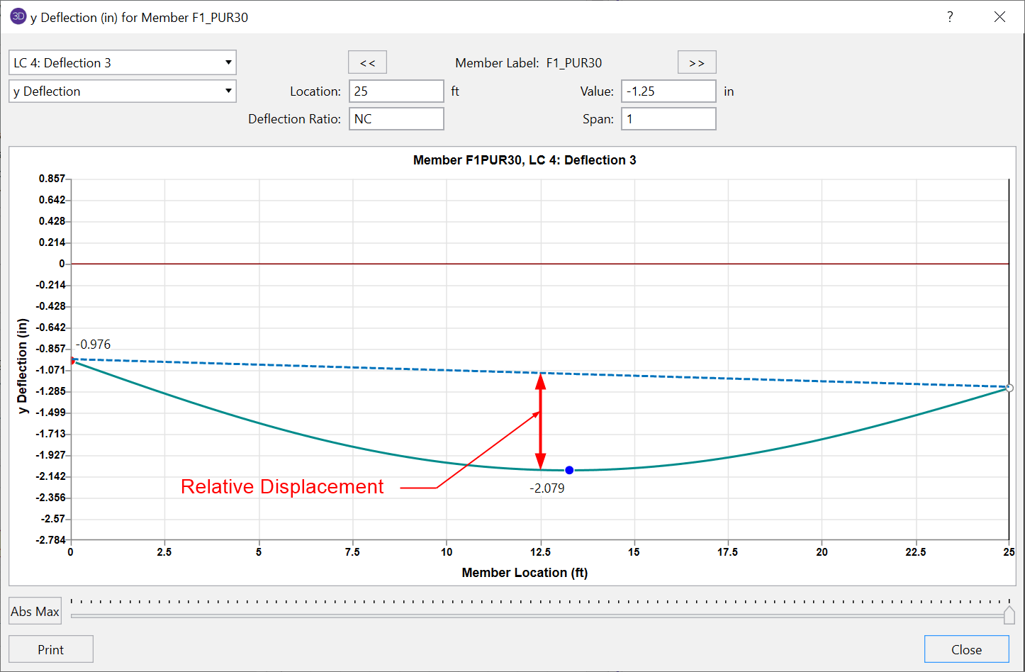
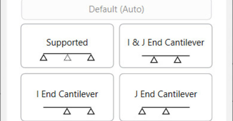
For a member supported on both ends, the maximum relative displacement will be the largest straight line distance (in the vertical y direction) between the deflected shape and the original undeflected shape.
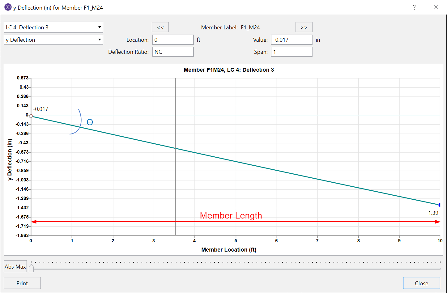
For members with a cantilever end, the location of the maximum relative deflection will be at the free end of the member. The displacement value is equal to the rotation at the supported end multiplied by the length of the member. Notice that in this case, the absolute deflection is equal to the relative deflection for a cantilever type member.
These relative deflection values are also used in the Beam Defl tab of the Member Deflections spreadsheet. These deflection ratio values will only apply to beams and the value for length that is used in the ratio will be the member span length as opposed to the full member length. These beam deflection ratios are able to be customized by using deflection ratio options.
For more information about beam deflections, search Beam Deflections in our Help File.
RISA-3D v16.0.4 introduces an enhancement that will allow for more...
After solving a model, you will see in the Member Deflections...
When solving a RISA-3D model with hot rolled steel members under the...