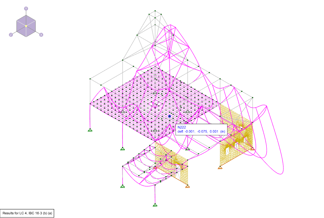
Deflection is a key tool for verifying whether your model was built correctly in RISA-3D. After solving, you can view the deflected shape to confirm if the deflections are within the expected range. If you notice abnormal deflections, use the following steps to troubleshoot the issue.
Steps for Investigating Large Deflections
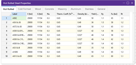
- Check Member Material Properties: Ensure that the correct material properties are assigned to your members. Incorrect materials can result in inaccurate stiffness and deflections.
- Review Member Sizes: Verify that your members are sized appropriately for the loads they are designed to carry. Oversized or undersized members can affect deflections significantly.
- Examine Member Connectivity:
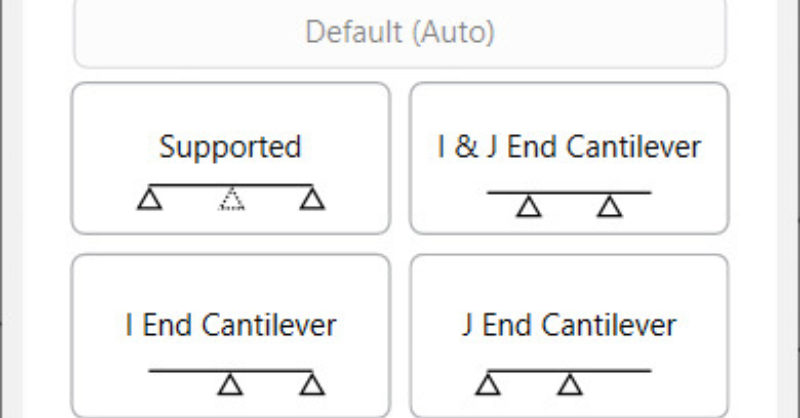
- End Releases: Incorrectly applied end releases can result in overly flexible members.
- Analysis Offsets: Verify that any analysis offsets are accurate, as these can influence the effective stiffness of the members.
- Plate Connectivity: Remember that plates only connect to other elements at their corner nodes, not along edges. Verify all plates are supported at their corners.
- Inspect Boundary Conditions: Ensure that your supports and restraints are correctly defined. Improper boundary conditions can lead to unexpected deflections.
- Review Applied Loading: Pay close attention to the magnitude and direction of your applied loads. Misapplied loads may cause unexpected deformations.
- Check Transient Loading (Member Area Loads): If you’ve used member area loads, keep in mind that these are distributed to the supporting members. You can visually inspect the distribution in the Transient Basic Load Cases created after the solution. For more details, refer to the Help File section on Transient Area Load.
- Verify Rigid Diaphragms: Ensure that rigid diaphragms are applied appropriately and check their influence on the deflection pattern of your model.
- Analyze Load Combinations: Review your Basic Load Cases spreadsheet, paying special attention to the X Gravity, Y Gravity, and Z Gravity columns. Misaligned gravity loads can cause unrealistic deflection results.
- Additionally, verify your Basic Load Cases (or Load Categories) are referenced correctly in the Load Combinations spreadsheet.
Additional Resources
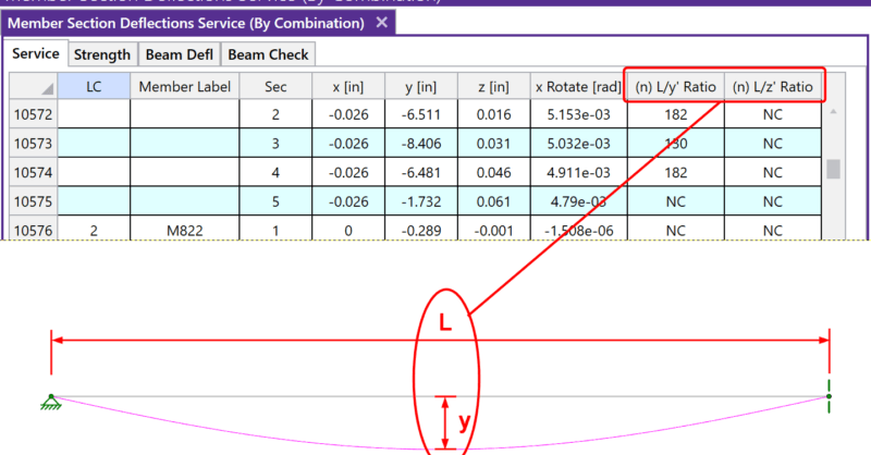
If you're designing with steel members and still noticing deflections greater than those predicted by traditional beam equations, check out the aricle linked below.
Have more questions about deflections in RISA-3D? Contact our support team or explore our Help File for further assistance.