


 By: RISA
How to Model a Two-Dimensional Component in RISA-3D
If you have ever tried to solve a two-dimensional model in RISA-3D,...
Finite Element Analysis (FEA) software has transformed the way engineers design. While it provides quick and easy analysis, it doesn’t guarantee accurate results for the requirements of your specific project. As the saying goes, “garbage in, garbage out”. Effective model validation is an integral part of the design process for engineers to make sure their design is up to standard.
Here are some practical steps for how to validate your FEA model as well as how RISA-3D can help streamline the process!
First and foremost, start by reviewing and addressing any warning or error messages. These alert the user to issues in the model that can compromise the accuracy of the results.
Not every warning message requires changes to the model. Some serve as background information for the engineer. In this case, the engineer should understand the noted condition and determine if it is relevant to their design.
RISA-3D helps engineers proactively identify modeling concerns by flagging critical issues during analysis and providing alerts accordingly. A common error message in RISA-3D is an instability warning. Instabilities can lead to inaccurate results and often point to missing restraints, unintended releases, or modeling assumptions that need review. Check out the article below to better understand these warnings and how to resolve them.
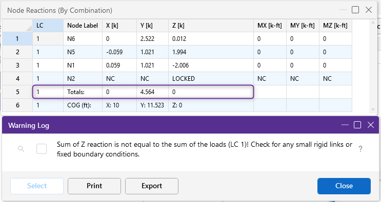
Even the most complex models must satisfy the basic concept of statics: the loading in must equal the loading out. The engineer must ensure the total applied loads equals the resulting support reactions in the model. An imbalance can occur for several reasons including an instability in the model causing the program to automatically lock a joint.
RISA-3D automatically completes this check during analysis and alerts the user if equilibrium is not satisfied. Engineers can verify directly by checking the result totals at the base of the Node Reactions Spreadsheet. This built-in validation reduces the risk of overlooked load path issues.
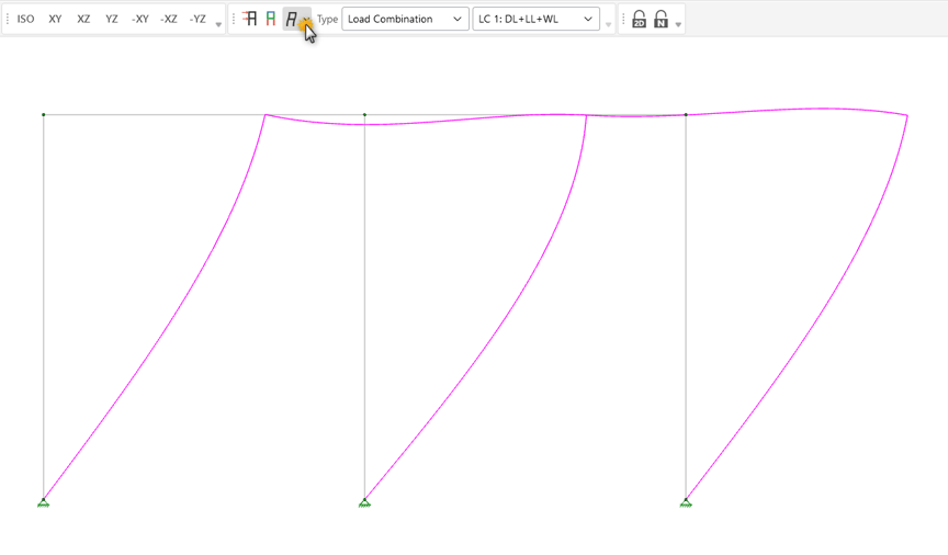
Reviewing the deflected shape can quickly reveal modeling errors by highlighting unexpected movement such as excessive member deflections or nodes flying off the page. It also provides immediate insight into the underlying behavior of the model including how the members are interacting with each other and how the load is being applied.
RISA-3D’s intuitive display provides the Deflected Shape toggle right at the top of the 3D View. With one click, engineers can confirm the movement of the structure and better understand its behavior.
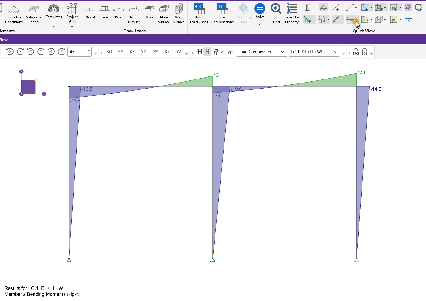
Load diagrams document how forces travel through the structure and provide a deeper understanding of the load paths and member interactions. Engineers can confirm the member end releases and load transfer between members by reviewing the axial, shear, and moment diagrams.
RISA-3D provides graphical and detailed reporting tools for member load diagrams. The graphical Member Forces tool allows for users to visualize the loads flowing through the model. Then the Detail Report option gives the engineer a seamless way to investigate a specific member.
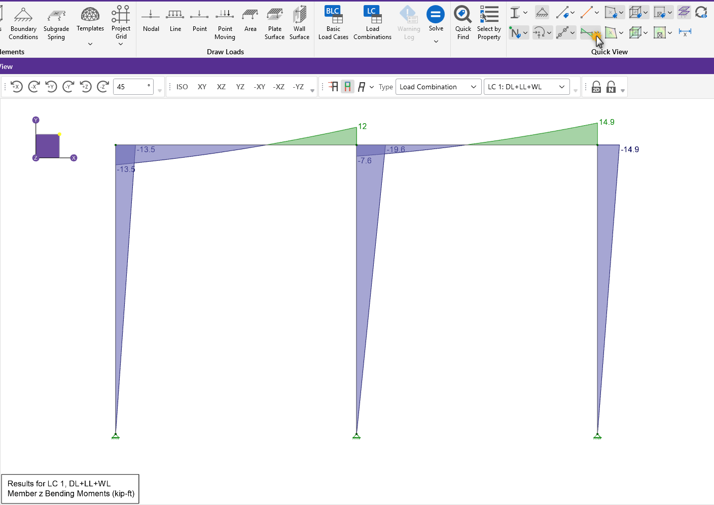
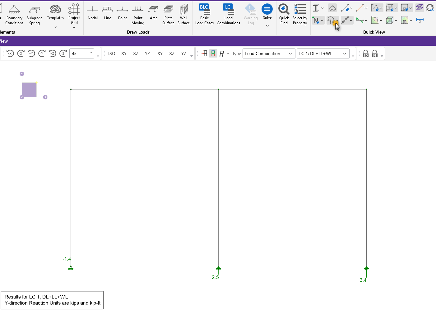
Beyond just checking the total reactions in step 2, the distribution of reactions provides insights into the model. Engineers should confirm the reactions align with the expected load path such as verifying uplift occurs at the lateral systems or that larger reactions align with where the majority of the load is located.
RISA-3D offers a fast graphical review option for reactions in the Quick View tool allowing engineers to confirm the load distribution efficiently.
Many FEA programs including RISA-3D provide member design along with structural analysis, enabling engineers to quickly check whether suggested member sizes align with expectations. As engineers gain experience, they will often have an intuition on the approximate member size based on the span and loading. If the program is suggesting members significantly different from an engineer’s expectations, it may indicate the model is not working as intended.
RISA-3D provides an intuitive color coding display to easily verify member unities. This feature allows engineers to quickly assess utilization across the model and identify outliers that warrant further review.
Last but not least, hand calculations remain a valuable tool to confirm the model’s results as it is a surefire way to ensure your expectations align with the actual results. While complex models can make this process more challenging, spot-checking key elements can provide additional confidence.
RISA-3D supports this manual validation by providing verification problems with every installation. RISA’s goal is to always provide transparency into the underlying calculations and reinforce trust in the provided results.
RISA-3D is designed to make engineers feel confident in their FEA model by making model validation faster, clearer, and more reliable. Want to learn more about how to verify your model in RISA-3D? Guide to: Reviewing your RISA-3D Model provides some additional best practices.
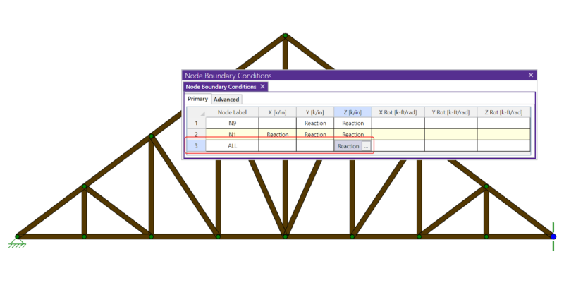
If you have ever tried to solve a two-dimensional model in RISA-3D,...

When working with RISA-3D, a structural analysis and design software, it's...
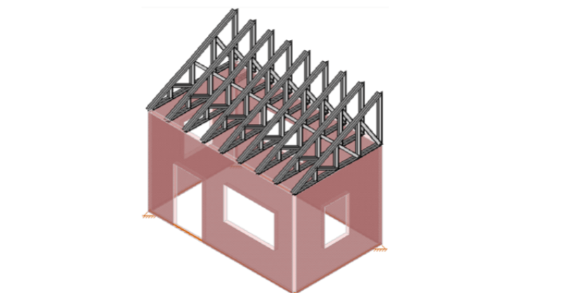
RISA-3D allows you to append, or merge, multiple models into a single...