By: RISA
Determining Masonry Wall Compression Block Depth Value "a"
When determining the Depth of Compression Block value of ‘a’ in a...
Wall panels in RISA-3D let engineers design and analyze multiple structural systems in a single model. Correctly applying boundary conditions at wall panels is critical to accurately represent the structure’s behavior. This FAQ answers common questions about how to set up wall panel boundary conditions and how RISA-3D handles them in the analysis.

1. Open the Wall Panel Editor
Double click on the wall panel in the 3D view to open editor
Use this editor to customize the wall panel including adding openings, changing materials, and assigning boundary conditions
2. Select Boundary Conditions
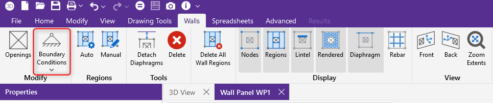
Click the Boundary Conditions button in the upper left corner under the Walls tab
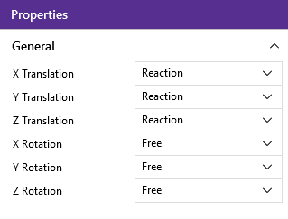
For custom restraints, set each degree of freedom (DOF) to Reaction or Free
3. Assign Boundary Condition at an edge
Click on a snap point along the edge of the wall where you'd like to apply the boundary condition
RISA-3D utilizes an internal mesh to analyze wall panels. The boundary condition is applied at the internal nodes created by this analysis mesh. This approach approximates a continuous condition while optimizing the run time of the model.
A couple of key points:
The wall mesh defaults to an approximate section size of 24 inches
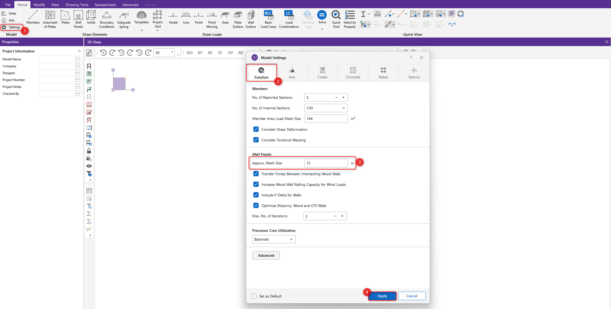
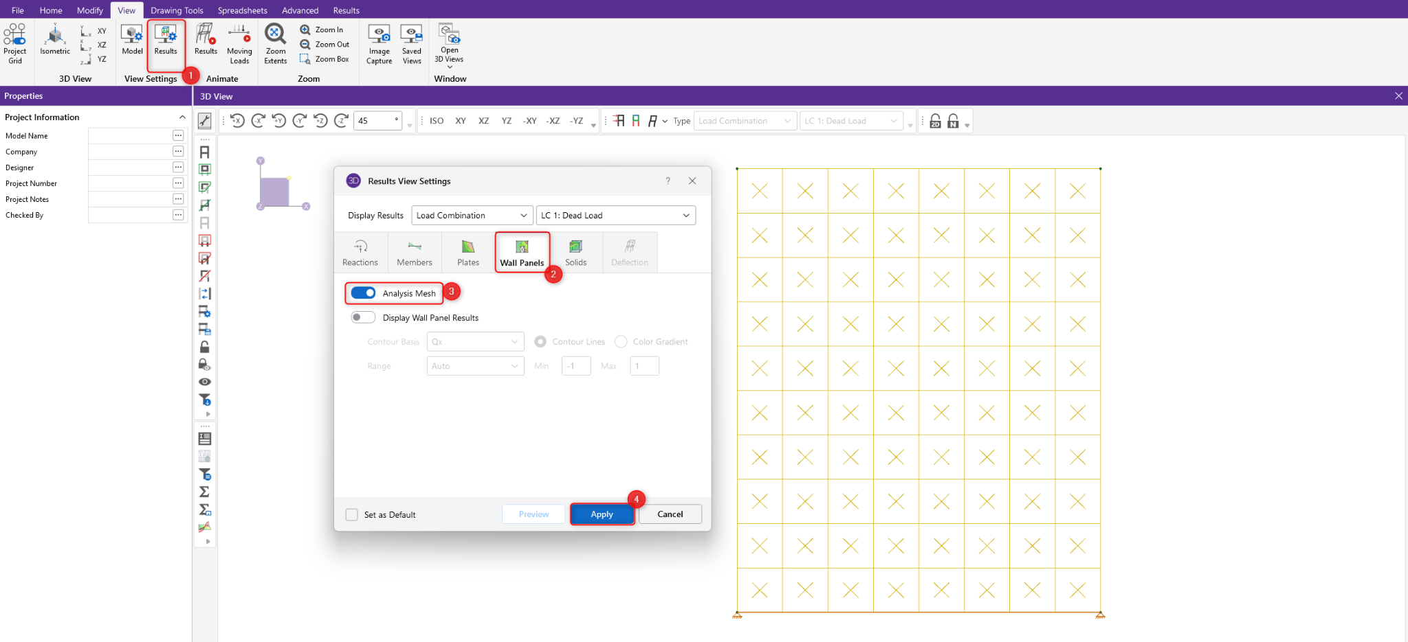
It is good habit to briefly review the mesh to confirm it aligns with your expectations prior to finalizing the results.
Both nodal and wall boundary conditions are external restraints that remove load from the model and generate reactions. The primary difference is how they are applied.
Nodal boundary conditions:
Applied to a specific node only
Shown in green in the model
Added directly from the Draw Elements section under the Home tab
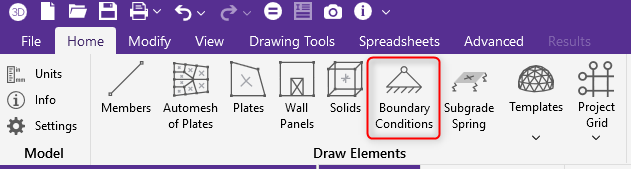
Wall boundary conditions:
Applied along the length of the wall
For most applications, the wall boundary conditions will provide a realistic restraint for the as-built condition by approximating a continuous support. However, both boundary conditions can be used to restrain a wall element so choosing the correct boundary condition will depend on the assumed behavior of the wall.
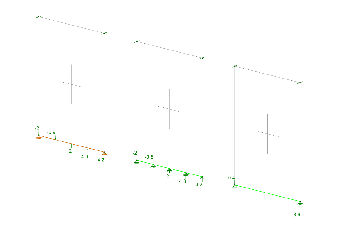
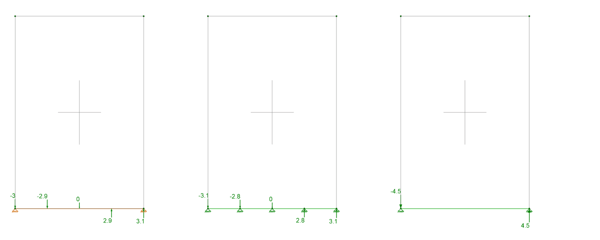
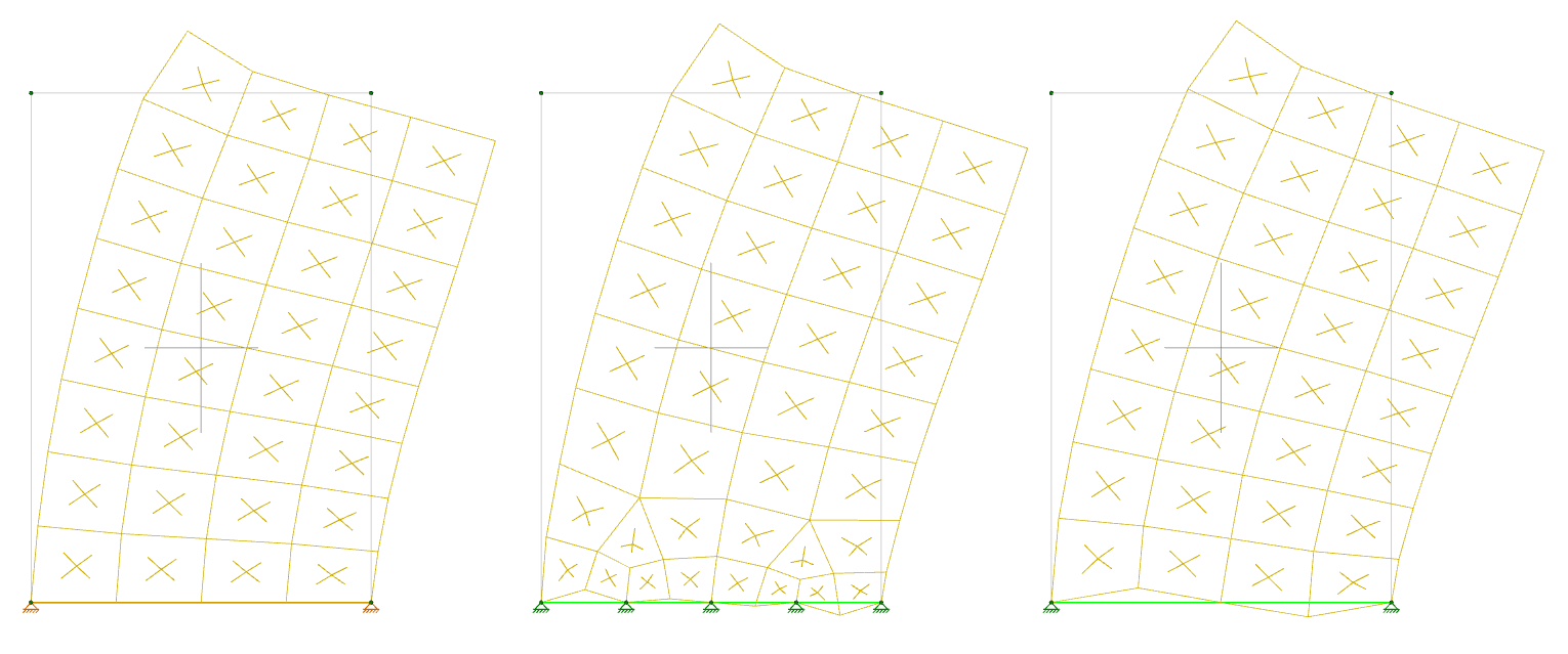
To better understand the different behavior based on the selected boundary conditions, see the side by side example below showing both the calculated reactions and the deflected shape of the wall panel. Here you can compare 3 different boundary conditions:
continuously pinned connection using a wall boundary condition
pinned connection using node boundary conditions spaced to mimic the wall panel mesh size
pinned connection using node boundary conditions only at end supports
To view the reactions at your wall panels:
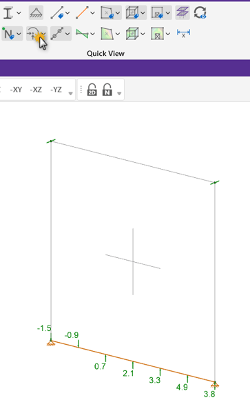
Use the Node Reactions spreadsheet for the total reaction at the base of the wall
For a deeper dive into interpreting these results, check out the article below which provides more details.
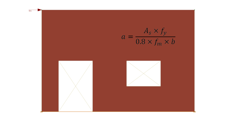
When determining the Depth of Compression Block value of ‘a’ in a...
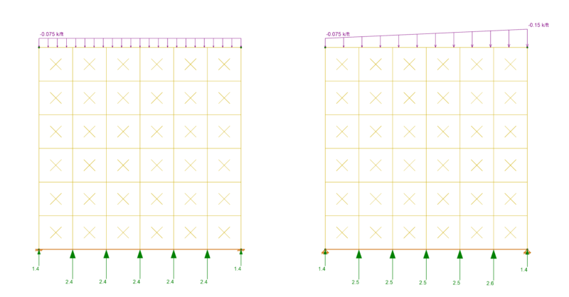
In the Node Reaction spreadsheet, all reactions from node-based...