


 By: Admin
Calculation of Forces in Seismic Brace Connections
Seismic brace connections are a bit different from other connection...
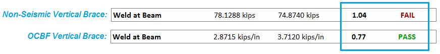
It is possible for seismic (OCBF or SCBF) vertical braced connections to have some limit state code checks lower than those for the same non-seismic connection.
This is due to the assumptions that RISAConnection makes when calculating the axial load in the beam. Non-seismic vertical brace connections only have a single beam axial load input value. Because seismic vertical brace connections require separate frame analyses of the various possible load directions, it is not appropriate to use a single input brace axial load for all load direction cases. Doing so could cause un-conservative results.
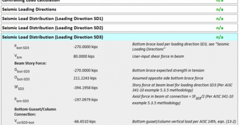
Therefore, RISAConnection calculates the beam axial load for each loading direction case.
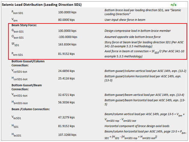
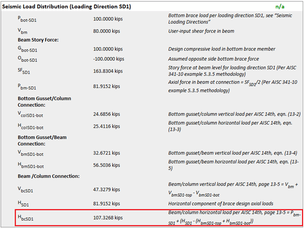
The beam axial load calculation is done for each applicable loading direction case. To see the details of these calculations, please see the Seismic Load Distribution on the new Seismic tab of the results report.
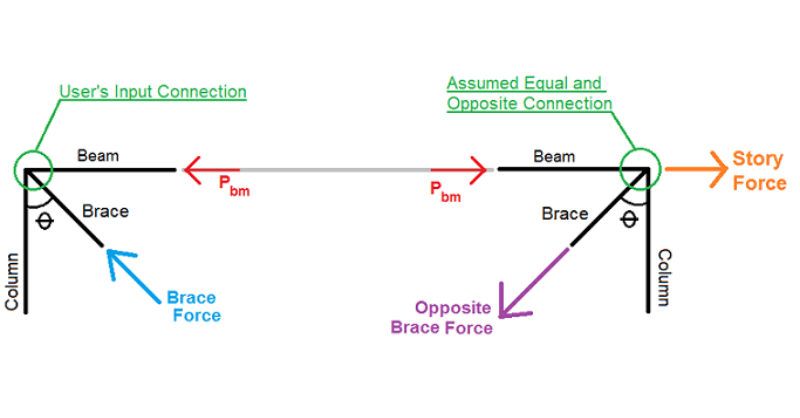
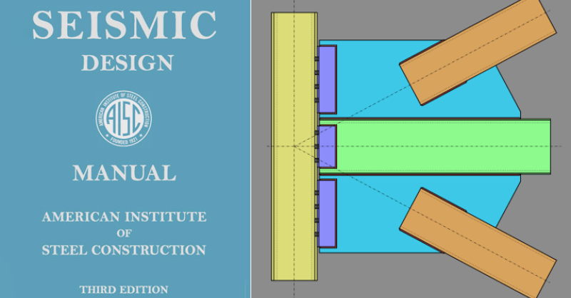
The procedure is based on that used in example 5.3.5 of the AISC Seismic Design Manual. It is determined using simple statics and the following assumption:
The input connection is mirrored on the other side of the bay with an equal and opposite braced connection.
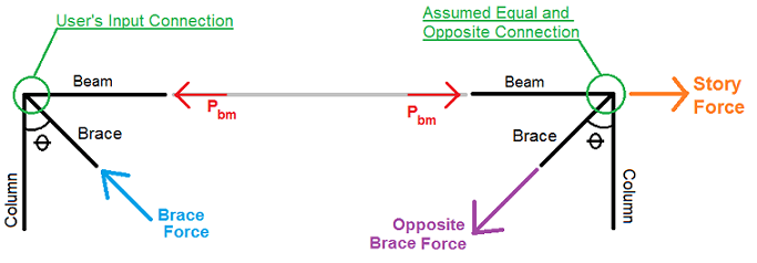
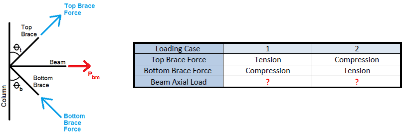
Assuming this assumption, the story force and axial force are calculated as:

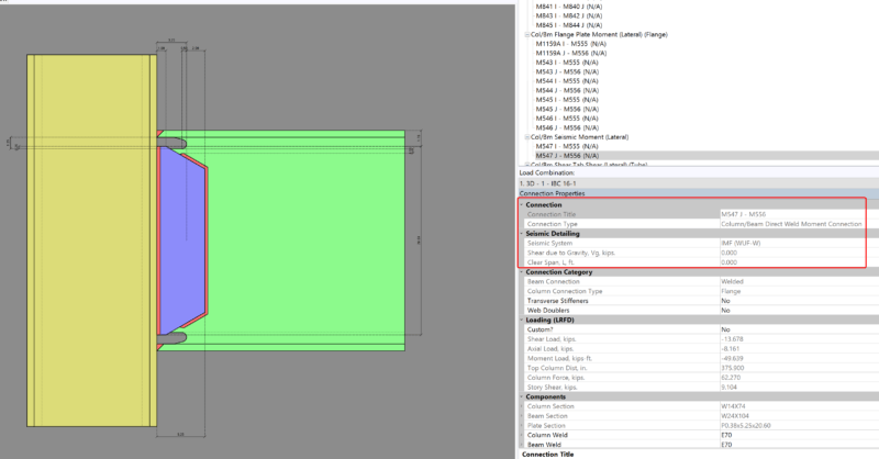
Once the beam axial load is calculated, it is used to calculate the axial force at the beam to column sub-connection interface. Per the Uniform Force Method, the axial force at the beam to column sub-connection is calculated as:

Hbrace = horizontal component of the brace force
Hgusset/beam = horizontal load at beam to gusset interface per UFM (AISC Steel Design Manual equation 13-5)
This is calculated for each of the applicable loading directions and then the design is done per the governing values; both in tension and compression, for the applicable limit states.
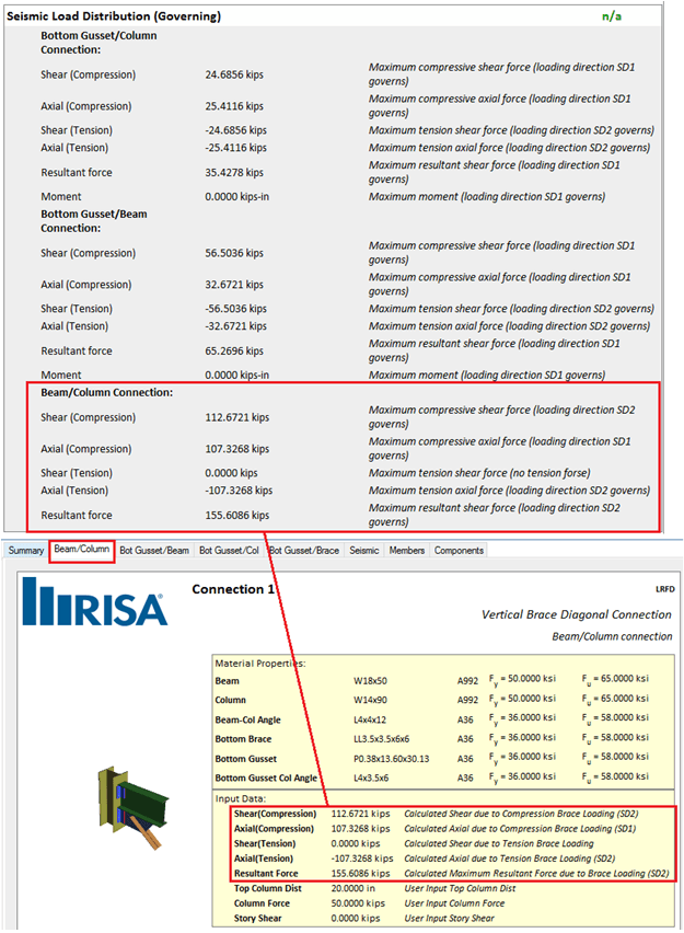
This means that the governing axial and/or resultant forces at the sub-connection interfaces can potentially be lower per the seismic analysis than they are for the same non-seismic connection.
Seismic brace connections are a bit different from other connection...
Design for seismic connection detailing is now available in...
RISAConnection v6 has introduced the ability to design vertical brace...