How Do I Detach a Wall Panel From a Diaphragm?
The ability to detach a wall panel from a diaphragm was a feature added...
When modeling building structures using steel or composite steel floors, engineers typically utilize rigid diaphragms to distribute lateral loads (wind and seismic) to lateral load resisting elements such as shear walls, moment frames and braced frames. Rigid diaphragms represent a plane of very high rigidity and distribute load to elements which connect to them solely based on the stiffness of the elements.
As a result, elements located within the extents of the diaphragm (such as wall panels) will have their forces “re-distributed” based on the relative stiffness of all the elements of that given level. Internally, this is accomplished by the fact that the rigid diaphragm is represented by rigid links that connect every node within the diaphragm (including those in a wall panel) at the level of the diaphragm.
The best way to investigate how a rigid diaphragm is impacting the results on a given wall panel stack is to utilize both the Wall Panel Forces spreadsheet and the Internal Force Summation Tool for Walls.
To easily review the results for a given wall stack, first select only the wall that you wish to evaluate the results for. Next, select the Filter Results button from the toolbar to the left of the graphical window to isolate the wall stack and see only the results for the selected members.

Next, open the Wall Panel Forces Spreadsheet to see the forces at the bottom of each of the wall panels that have been selected. These forces in the stack are not cumulative due to the rigid diaphragms at each level pulling force out of the wall panel and re-distributing them.

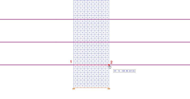
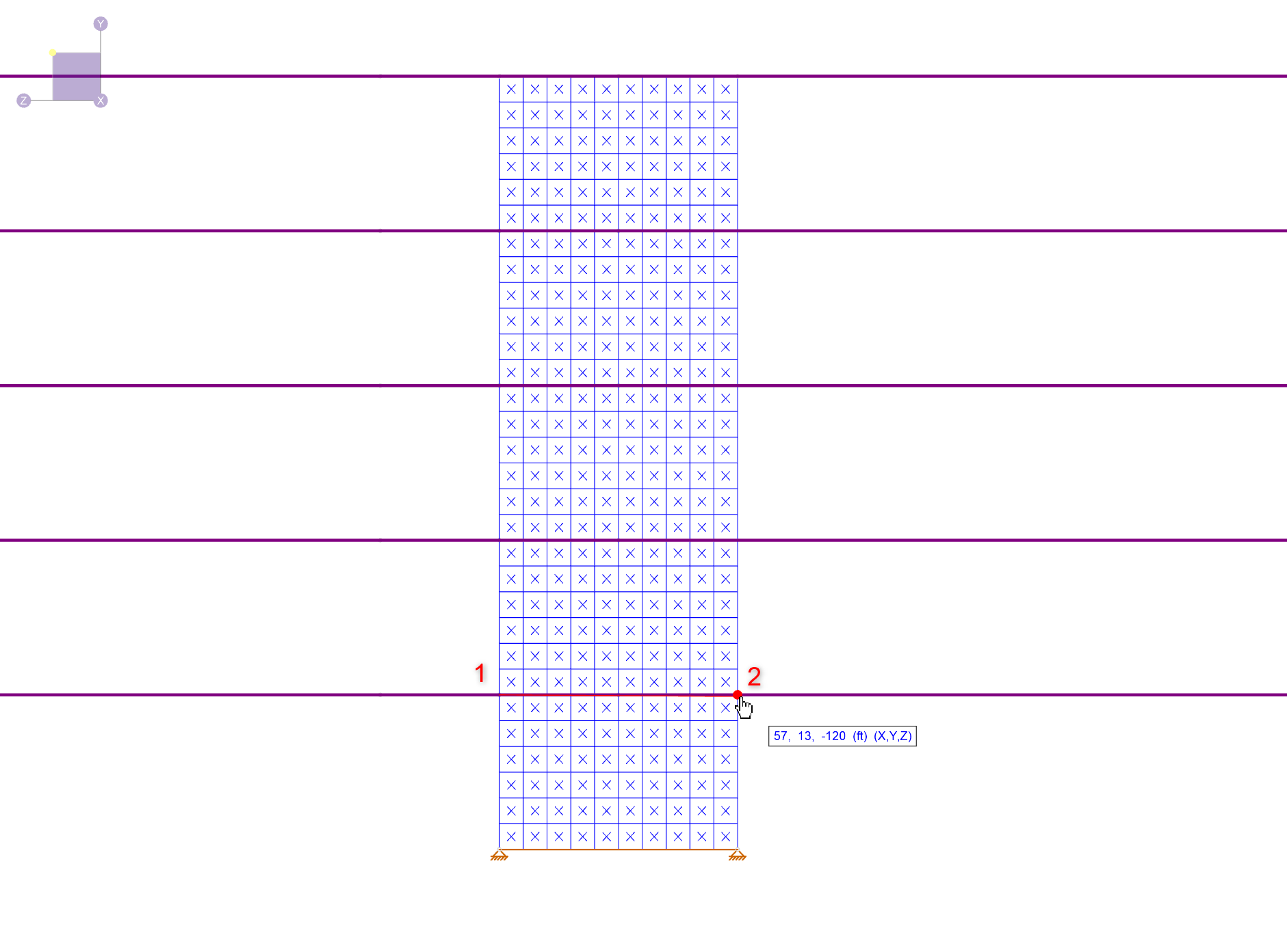
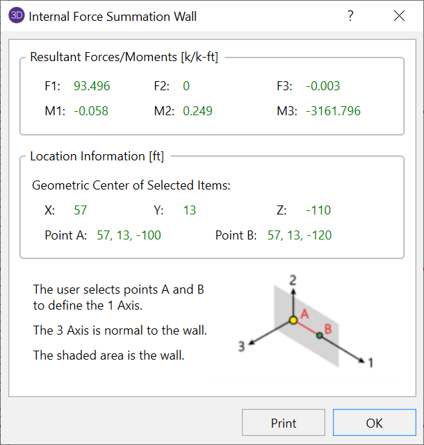
The best way to verify the results found in the Wall Panel Forces spreadsheet is to utilize the Internal Force Summation Tool for Walls by clicking the Wall button found in the toolbar on the left side of the graphical window. Then click two points (shown in the below image as 1 & 2) to define the cutting line. In this example, the edges of the wall at the 13ft elevation are chosen. This will then launch the force summation dialog box and the result for F1 can be compared to the value for “x shear [k]” found in the above spreadsheet (the values are exactly the same).
For more information about rigid diaphragms or the Internal Force Summation Tool click the link below:
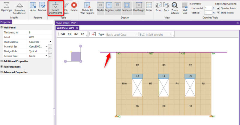
The ability to detach a wall panel from a diaphragm was a feature added...
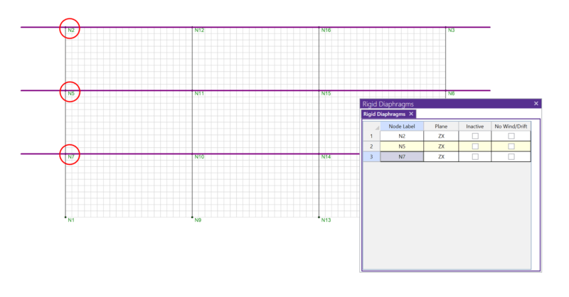
In RISA-3D, rigid diaphragms can be added using the Diaphragm...
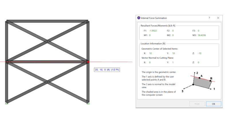
When using rigid diaphragm analysis in RISA-3D it can be useful to...