


 By: Admin
How to Model Tension-Only Bracing in RISA-3D
Before reading this, be sure to check out the article linked below on...
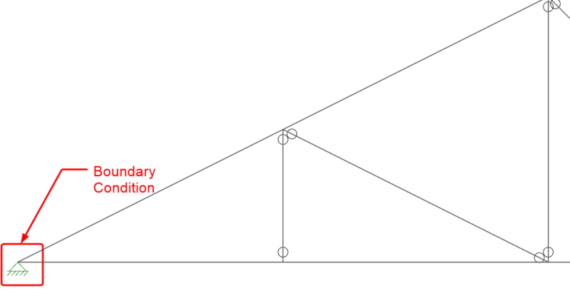
When it comes to trusses in RISA-3D, boundary condition definitions (pin vs. roller) can make a huge difference. Let’s take an example of a typical roof truss. Note that a pin-pin boundary condition has been applied to the ends.
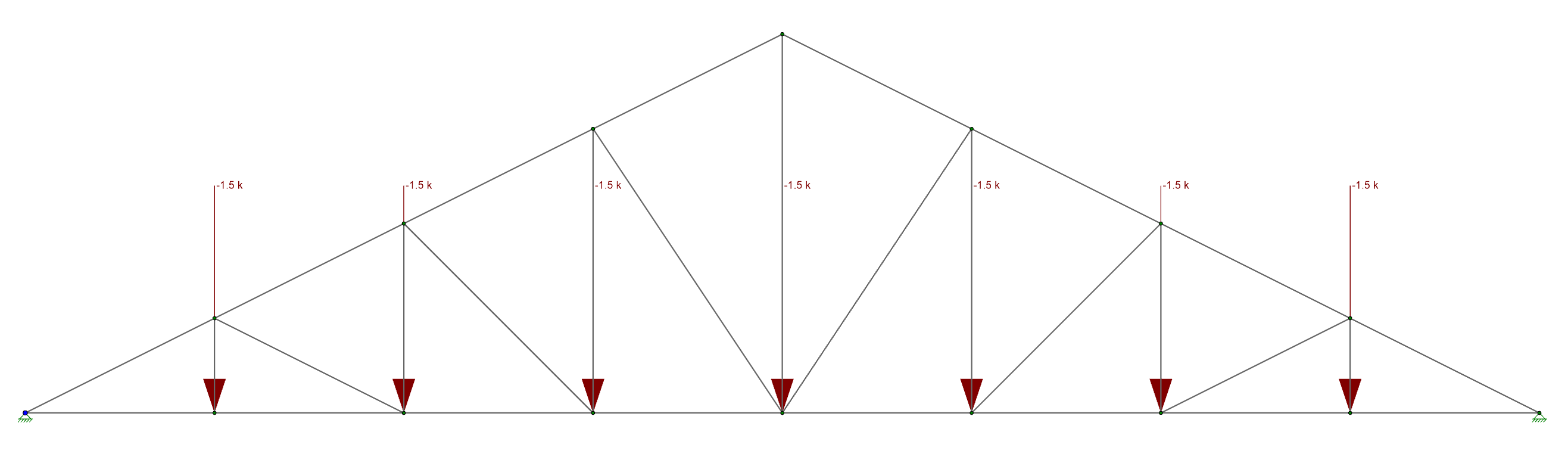
First we must make sure to give the truss out of plane stability by setting this up as a 2D Model within RISA-3D. Then, after solving, you will find that this is not at all behaving like a truss. There are huge axial compression forces in the top chords, and there is no tension in the bottom chord. The reason is that the pin-pin boundary condition prevents the bottom chord from elongating.
If it cannot elongate then there cannot be axial strain in the member. You will recall from your Mechanics of Materials class that if there is no strain there cannot be stress, and therefore there can be no axial tension in the bottom chord. The program works out statics the only way it knows how by using arching action with the top chords instead of looking at truss behavior. Now instead try a roller boundary condition on one end of the truss:
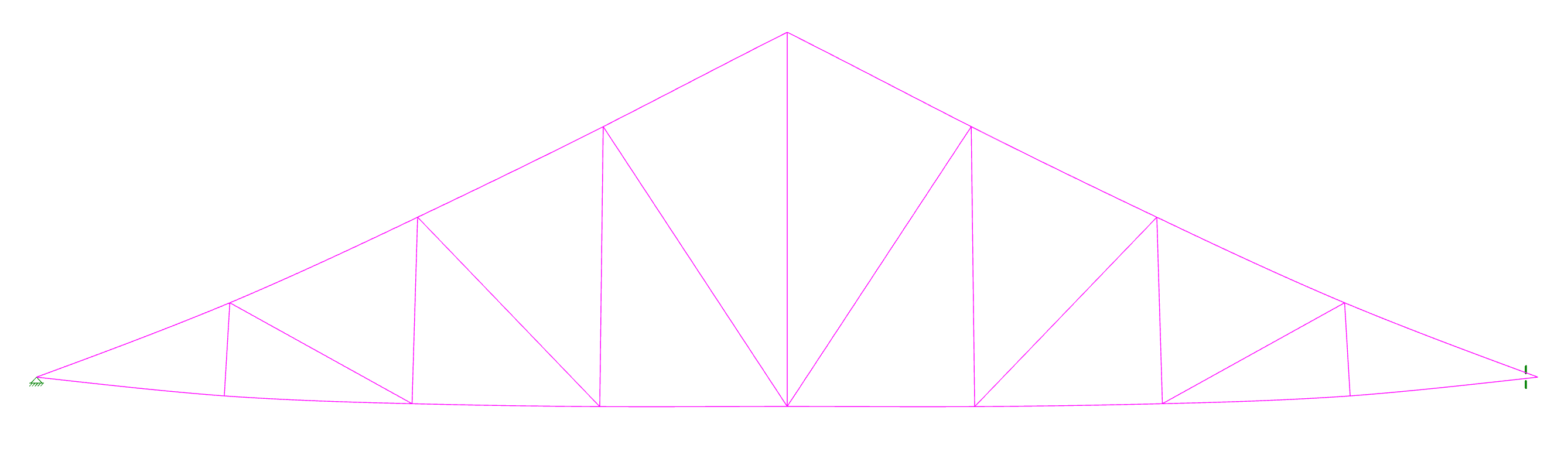
Now the bottom chord is experiencing a tension roughly equal to the compression in the top chords, and all of the member forces conform to what an experienced engineer would expect. However, just because we want the truss to behave in a pin-roller fashion does not mean that it will in real life. That will all depend on how the truss is connected to its supporting elements. To confirm that this behavior is legitimate we should really look at the lateral deflection of joint N3. If the deflection is large we may need to rethink our analysis:
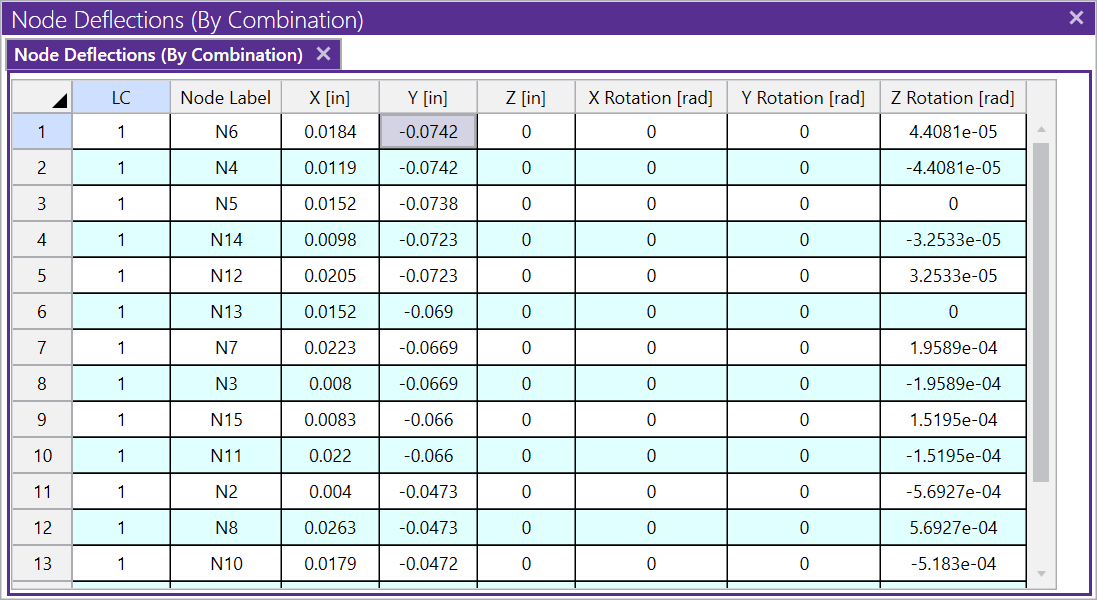
Fortunately the deflection is less than 1/16”, which is a perfectly reasonable deflection for almost any type of connection, so the pin-roller model will accurately reflect the real-life condition.
Before reading this, be sure to check out the article linked below on...
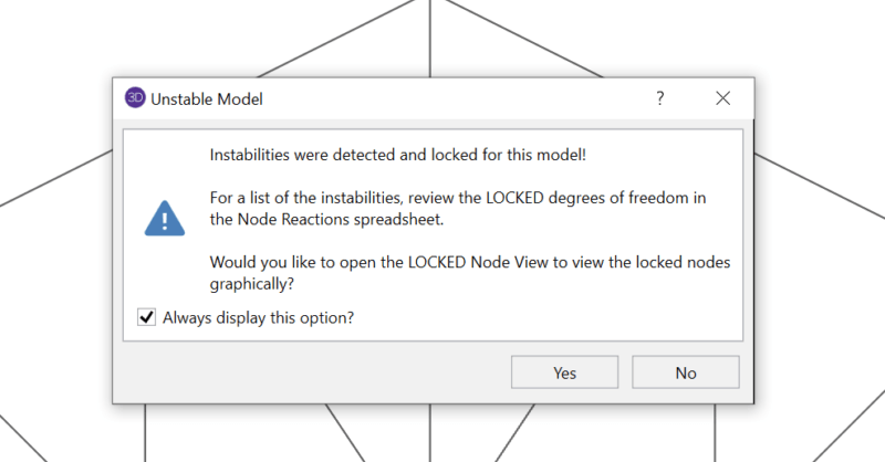
Have you ever received an instability warning when running a three...
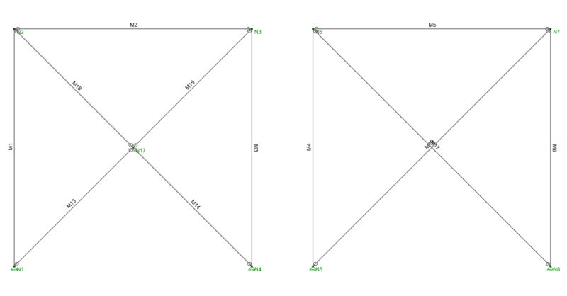
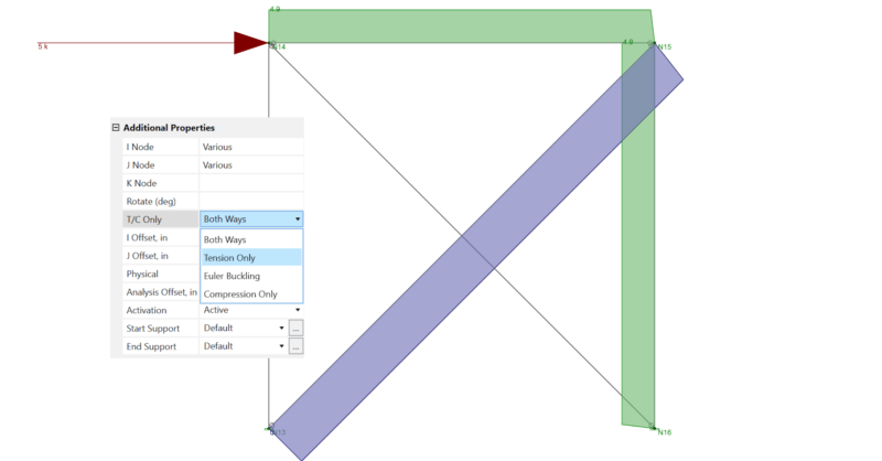
There are several tips to modeling X-Bracing within RISA-3D that can...