


 By: Admin
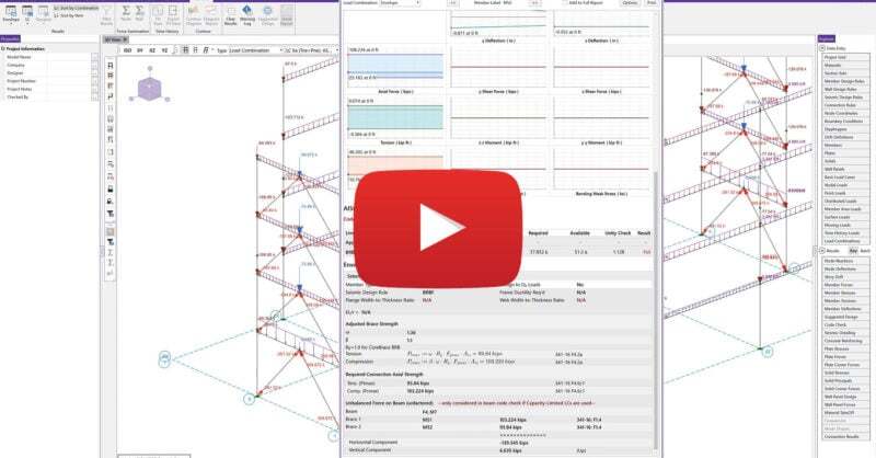
Video: Design Buckling Restrained Braced Frames in RISA-3D
The ability to design buckling restrained braced frames has been added...
With the release of RISA-3D v19.0.2, you can now design special concentrically braced frames (SCBF) as well as buckling restrained braced frames (BRBF) according to the capacity-limited design. The objective of capacity-limited design is to ensure columns and beams in braced frames are designed to resist the capacity-limited seismic load effect based on brace expected strengths.
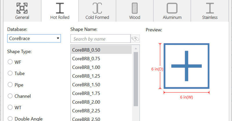
The steps below illustrate the workflow for SCBF capacity-limited design in RISA-3D. For more information regarding design of BRBF in RISAFloor and RISA-3D, please refer to the following article:

Available codes for the capacity-limited design of members include:
AISC 360-10 (AISC 341-10)
AISC 360-16 (AISC 341-16)
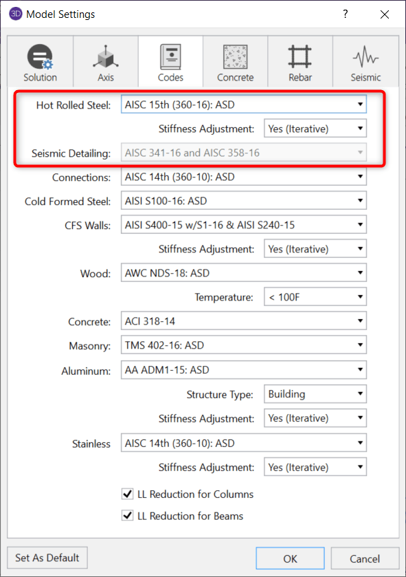
If AISC 341-10 is selected, the members will be designed for the lesser of the capacity-limited and overstrength load combinations. If AISC 341-16 is selected, the envelope load combination will be used for design.
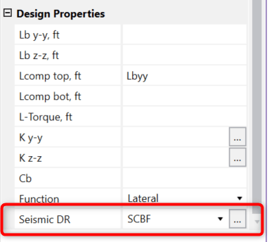
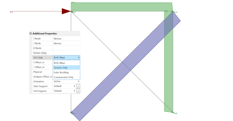
Whether you’re integrating your model from RISAFloor or if you’re creating your model natively in RISA-3D, you will need to be sure to assign the proper seismic design rules to your members for capacity-limited load combinations to be considered. You can define your seismic design rules in the Seismic Design Rules spreadsheet, and assign the defined rules to members within the Properties Panel under the Design Properties section.
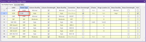
A comprehensive list of seismic design rules can be found in the Seismic Design Rule spreadsheet. A critical component in the designation of Seismic Design Rules is the Frame Type. In order for the braced frames to be designed according to the capacity-limited design, the SCBF or BRBF frame type must be selected.
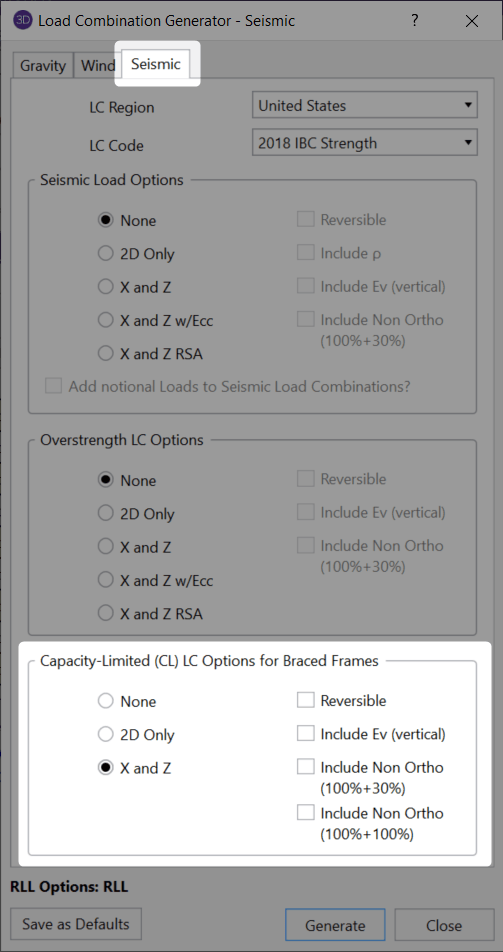
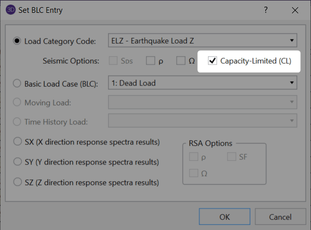
Capacity-limited load combinations can be generated automatically using the Load Combination Generator or you can manually enter in the Basic Load Case with the option to consider the Capacity-Limited Design checked.
Analysis of the capacity-limited considers two scenarios for each load combination:
The brace under full tension and full compression (Tne+Pne)
The brace under full tension and post-buckling compression (Tne+0.3Pne)
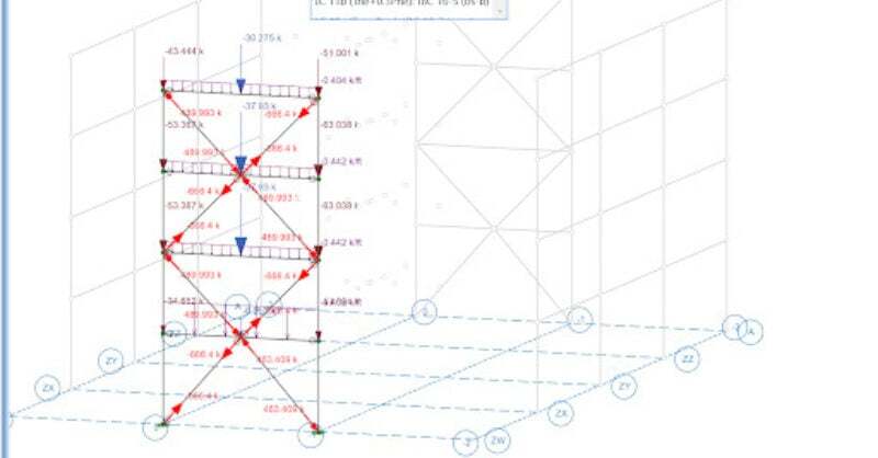
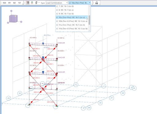
Once a model has been solved it is possible to display the magnitude and direction of the capacity-limited forces in the 3D view. To view these forces, simply choose one of the capacity-limited load combinations from the drop down menu.
With the implementation of the capacity-limited design, beams and columns are able to be optimized for special concentric braced frames. This also includes the consideration of unbalanced forces on the beam in the V and inverted V braced frame configuration.
The ability to design buckling restrained braced frames has been added...
The ability to design buckling restrained braced frames has been added...
Before reading this, be sure to check out the article linked below on...