Understanding The Moment of Inertia for Different Shapes

Understanding The Moment of Inertia for Different Shapes

Key Takeaways

  • Moment of inertia defines how much a beam will sag (deflection), not necessarily when it will break (stress), though the two are related.
  • In a rectangular section, the height (h) of the member is cubed in the formula. Doubling the width of a beam doubles its stiffness, but doubling its height increases its stiffness eightfold.
  • Most shapes have a strong axis (the orientation that resists bending best) and a weak axis.
  • Because it involves area multiplied by distance squared, the units are always length to the fourth power (e.g., in4 or mm4).

In structural engineering, the Area Moment of Inertia (I) is a geometrical property of a cross-section that describes how its mass or area is distributed relative to a central axis. It is the primary measure of a member's stiffness and its ability to resist bending and deflection.

Unlike total area (which simply tells you how much material you have), the moment of inertia tells you where that material is located. The farther the material sits from the neutral axis (the center of bending), the higher the moment of inertia becomes.

This is why an I-beam is so effective: it places the bulk of the material in the flanges, as far as possible from the center, to maximize resistance to bending.

Why Geometry Matters and The Concept of Stiffness

To visualize moment of inertia, imagine a standard wooden 2 x 4 board used as a bridge across a small gap.

  • If you lay the board flat (the wide side facing up), it will sag significantly under your weight. It is bending about its weak axis.
  • If you turn the board on its edge (the narrow side facing up), it becomes incredibly rigid and barely deflects. It is now bending about its strong axis.

The amount of wood hasn't changed, but by moving the material farther away from the center of the board, you have drastically increased the Moment of Inertia. This is why structural steel is shaped into "I" or "H" beams; it places the bulk of the material (the flanges) as far as possible from the center (the neutral axis) to maximize stiffness with minimal weight.

Fundamental Formulas and Calculations For The Moment of Inertia in Different Shapes

Engineers rely on a set of standard formulas to determine the inertia of common shapes. The most important of these is the rectangular section, where the height of the member is cubed, highlighting why depth is the most critical factor in beam design.

1. Rectangular Sections

The "bread and butter" of structural calculations:

  • Strong Axis (Ix): bh3/12
  • Weak Axis ($I_y$): hb3/12

2. Hollow and I-Shaped Sections

For shapes like steel tubes or wide-flange beams, the calculation involves taking the "gross" outer rectangle and subtracting the "hollow" inner areas:

  • General I-Beam Formula: I= BH3/12 - bh3/12

3. Circular and Polar Inertia

For columns or shafts, the area is distributed equally in all directions:

  • Solid Circle: I = 𝜋D4/64
  • Polar Moment of Inertia ($J$): This measures a member's resistance to torsion (twisting) rather than bending, calculated as J = Ix + Iy

Modeling and Software Verification

In a modern engineering workflow, calculating the moment of inertia for complex, unsymmetrical, or built-up sections by hand is a high-risk use of time. Software like RISA-3D or RISACalc automates these properties.

The Complexity of Concrete

Concrete design adds a layer of complexity: cracking. When a concrete beam bends, the tension side cracks, effectively removing that area from the moment of inertia calculation.

  • Gross vs. Effective: Engineers must distinguish between the "Gross" inertia (Ig)and the "Effective" inertia (Ie).
  • Code Compliance: Software automatically applies ACI 318 reduction factors (e.g., 0.35Ig for beams) to ensure that deflection results in the model reflect the real-world behavior of cracked concrete.

Handling Non-Symmetrical Shapes

For T-beams, L-shapes, or custom channels, the software utilizes the Parallel Axis Theorem to find the neutral axis (centroid) and then sums the inertia of each component. This ensures that even the most irregular architectural features are modeled with accurate stiffness.

If your model is returning "Stability" errors or excessive deflections, the first thing to check is member orientation. A beam accidentally rotated 90° is bending about its weak axis, losing roughly 70-80% of its intended stiffness.

Mastering Structural Stiffness

The moment of inertia is the tool that allows engineers to span longer distances and reach higher heights without simply "throwing more material" at the problem. When you understand how to manipulate cross-sectional geometry, you can optimize for both safety and economy.

Are you ready to stop the manual math and start optimizing? RISA handles the heavy lifting of section property analysis and code-compliant deflection checks so you can focus on the big picture.

Start your free trial of RISA-3D today and move from manual formulas to professional design automation.


You may also be interested in

 
Why does my slab deflection increase using ACI 318-19?
DECEMBER 21, 2021

Why does my slab deflection increase using ACI 318-19?

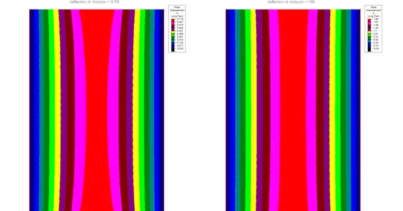
Since the release of RISAFloor v15 and ADAPT-Builder v20, both which...

Read More
Structural Analysis Considerations for Industrial Steel Structures
JANUARY 27, 2026

Structural Analysis Considerations for Industrial Steel Structures

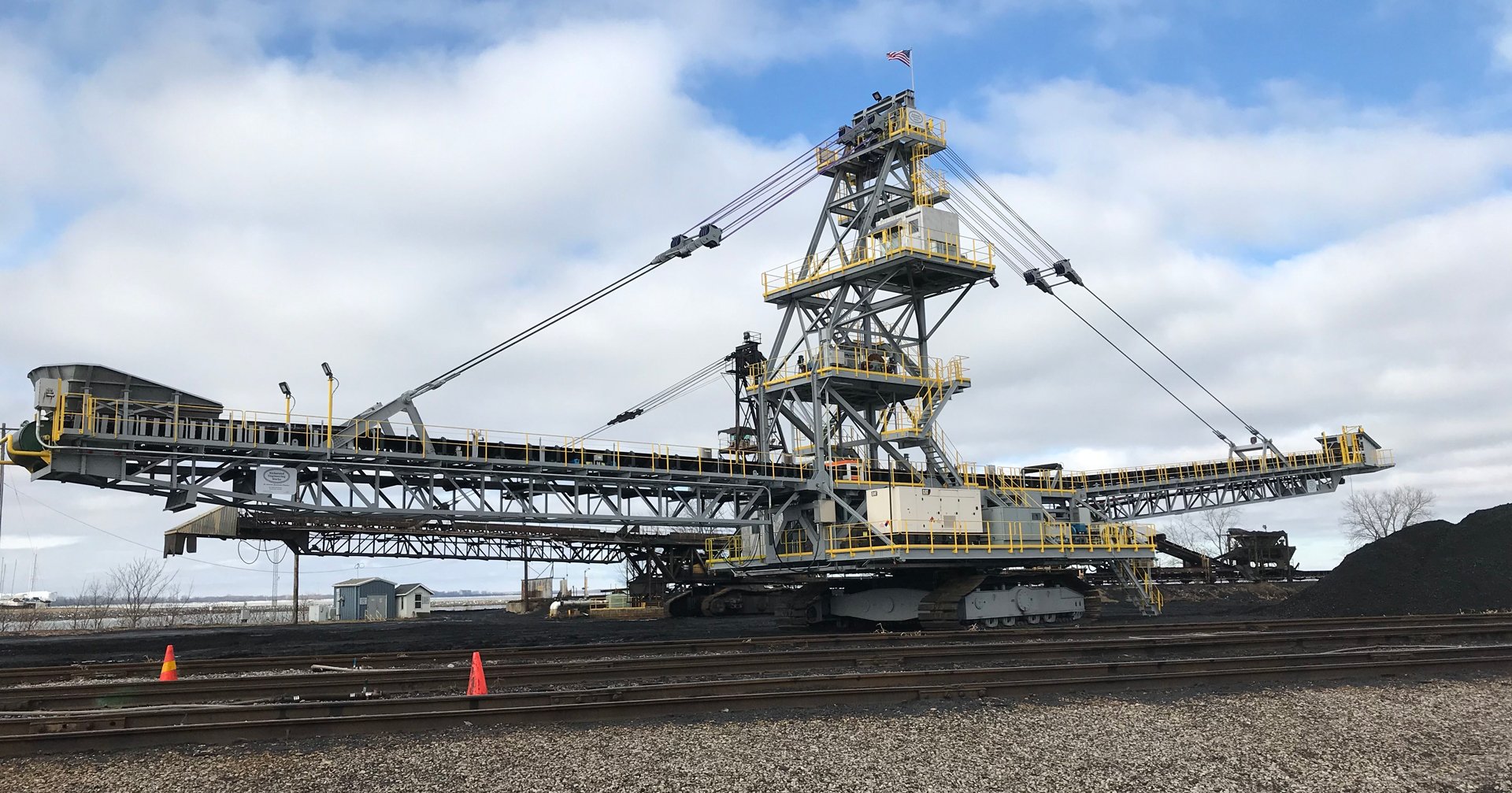
Industrial steel structures—such as pipe racks, material handling systems,...

Read More
LIVE ONLINE TRAINING: Introducing the RISA-3D Quick Start Course
OCTOBER 15, 2020

LIVE ONLINE TRAINING: Introducing the RISA-3D Quick Start Course

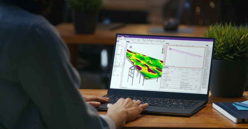
The Quick Start Course is a 4-hour introduction to the basic features...

Read More