


 By: Admin
Tips & Tricks for Modeling in ADAPT-Builder
Modeling complex structures in any structural analysis and design...
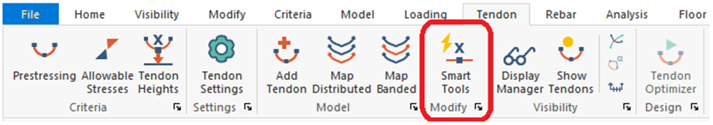
ADAPT-Builder v21 now includes a new set of Smart Tools that assist the user in efficient modeling and modification of tendons. These tools include smart creation of tendons where the tendon spans and shapes are determined by the program based on the location of support lines or banded tendons within the model. The new Smart Tools can be found within the Tendon Ribbon when the program is opened in PTRC mode.
The Smart Tools are typically used after generating banded tendons using the "Map Banded Tendon" tool or through user entry of banded tendons. However, the Smart Tools are available for use at all times and clicking on the Smart Tools icon will launch the Smart Tendon Editor.
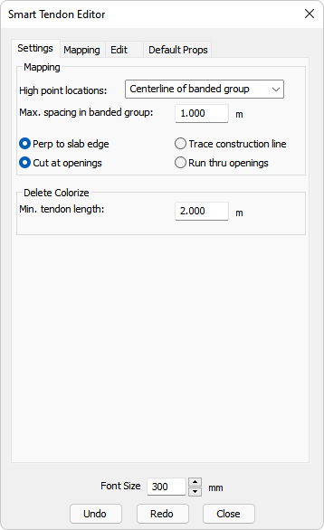
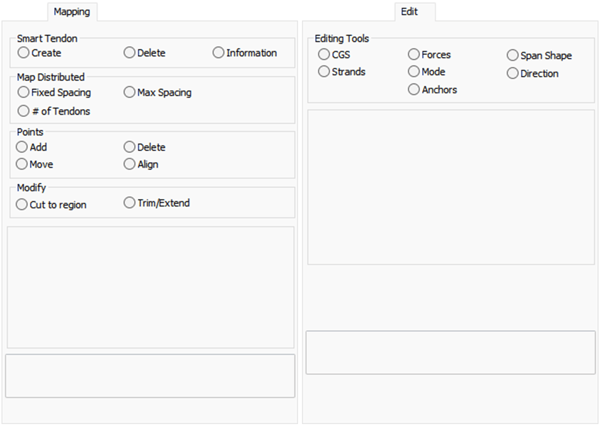
The Smart Tendon Editor consists of four tabs (as shown below). Users would first define the criteria in the Settings and the Default Props tabs and then utilize the Mapping tab to create tendons.
Settings - allows users to defined the behavior of the tendons created and utilized in Mapping tab
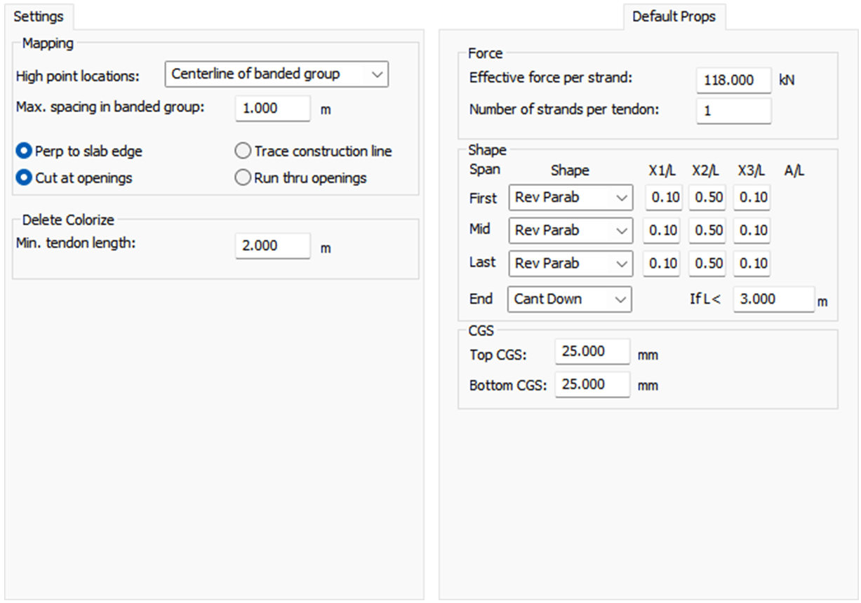
Default Props - allows users to set default properties for the tendons created and utilized in Mapping tab
Mapping - allows users to select input methodology and distribution for the creation of tendons based on previous criteria
Edit - allows users to edit various properties and criteria of the tendons (used in plan view)

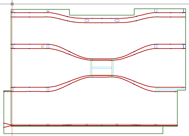
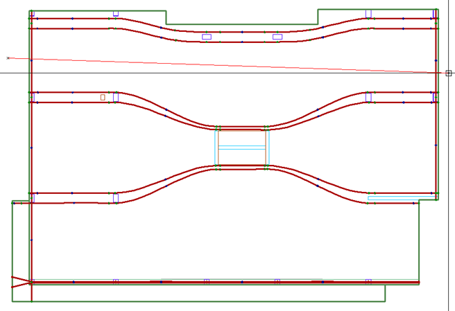
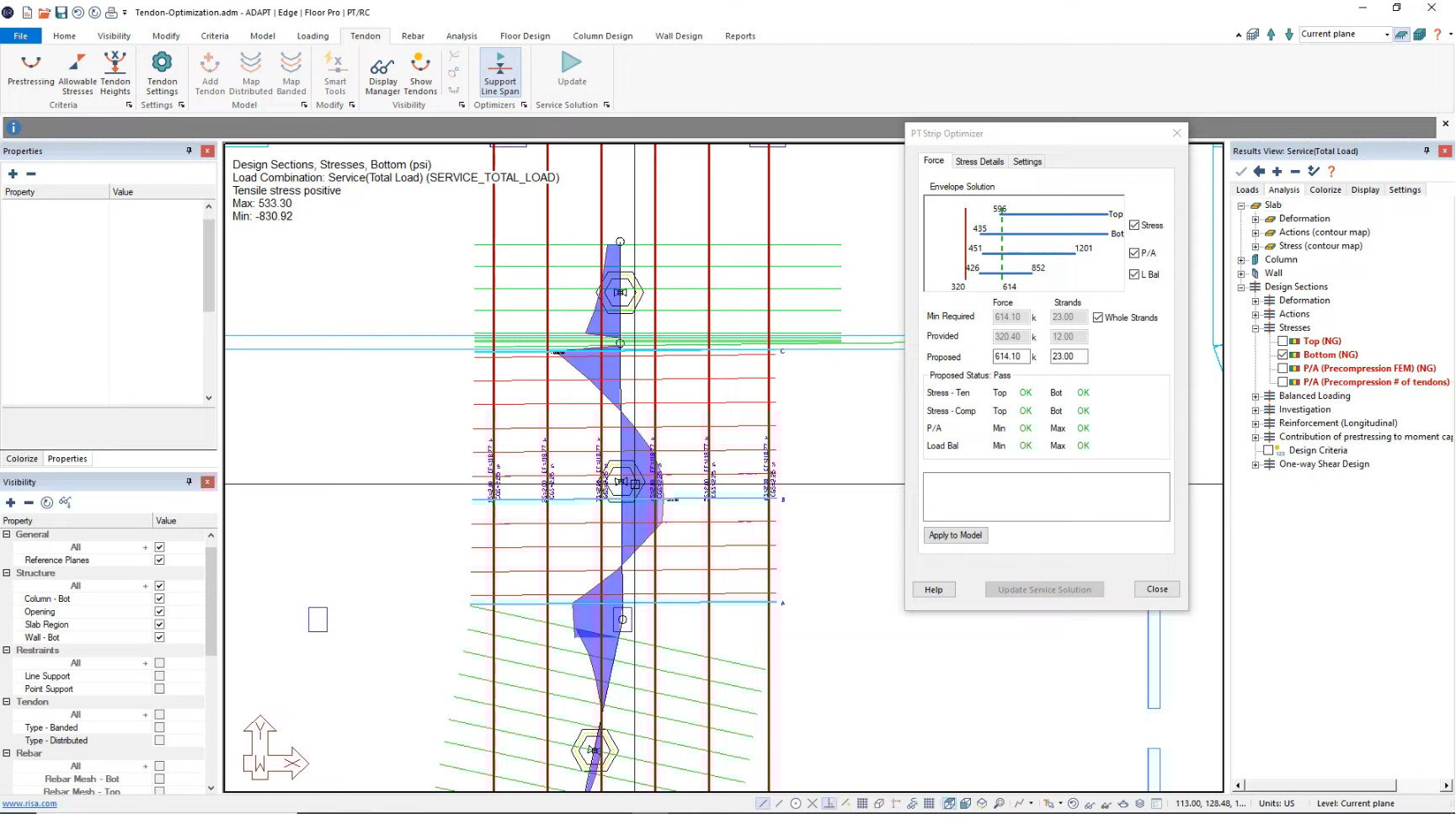
Once the basic settings and defaults properties are established, the Mapping tab can be used to create tendons. Under the Smart Tendon category, we have options to create or delete tendons, as well as an option to report information about tendons. To create tendons, click on the create button, the program will then prompt the user to draw a construction line for the tendon. Using the ADAPT-Builder tutorial model to demonstrate the tendon creation tool we can draw a construction line on the left side of the structure as shown below.
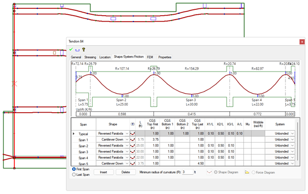
Once the construction line (red line) is drawn the program will create the tendon. The tendon will have a high point over the bands or support lines depending on the options selected on the Settings tab. We can see in the below screen shot the program created a tendon with 5 spans and the profile follows the settings that were set up in the Default Prop. Tab of the Smart Tendon Editor window.
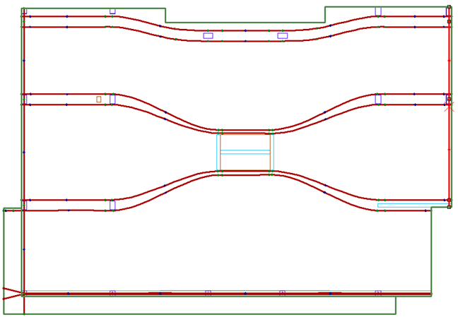
Users can now do the same on the right end of the model to define the last tendon. Once finished a model with banded tendons and two distributed tendons within the model is created (shown below).
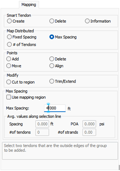
The two distributed tendons created above will act as our boundary tendons for the mapping procedure. We can now select one of the options under the Map Distributed section of the Mapping tab. The choice of options are to map the tendons based on Fixed Spacing, Max Spacing, or Number of Tendons. For this example, we will choose the max spacing option with a max spacing of 4 feet as shown below. Note there is a "map to region" option.
With the options selected and setup for the required spacing, we can map our tendons. To map the tendons the user can draw a construction line crossing the two boundary tendons as shown below.
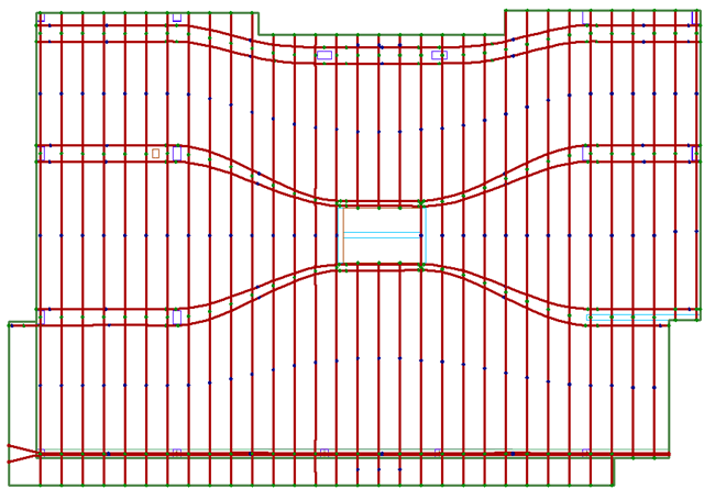
Once the red construction line is drawn, the program will automatically create the tendons between the boundary tendons using the slab edge as the extent boundary for the tendons. The tendons will automatically adjust for the number of spans and if the option to cut tendons at openings is used the program will consider the opening and split the tendon so that it does not run through the opening. The tendon layout after completing this step should now look similar to the below screen shot.
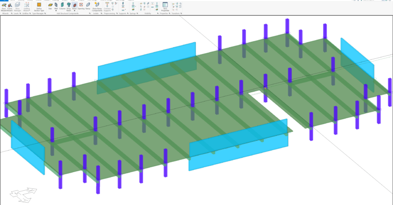
Viewing the tendons in an isometric view with an exaggerated z-scale we can see the layout in full, with profiles as shown below.
The user now has the option to modify properties of the tendons using the tools found in the Mapping and Edit tabs of the Smart Tendon Editor. Adding, deleting and modifying control points can be done through the Mapping tab. In addition, the Mapping tab has tools for cutting tendons to a specific region. Other options for modifying tendons are available in the Edit tab of the Smart Tendon Editor.
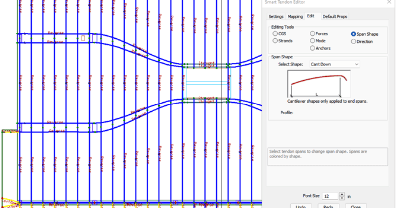
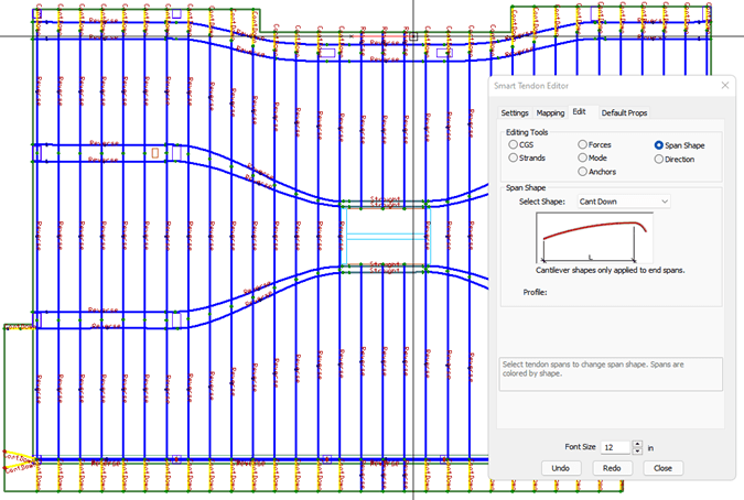
The user can use these tools to modify the tendon property that is selected in this window. For example after mapping the tendon users can click the "Span Shape" button and the program will show the span shapes graphically on screen using different colors as shown below.
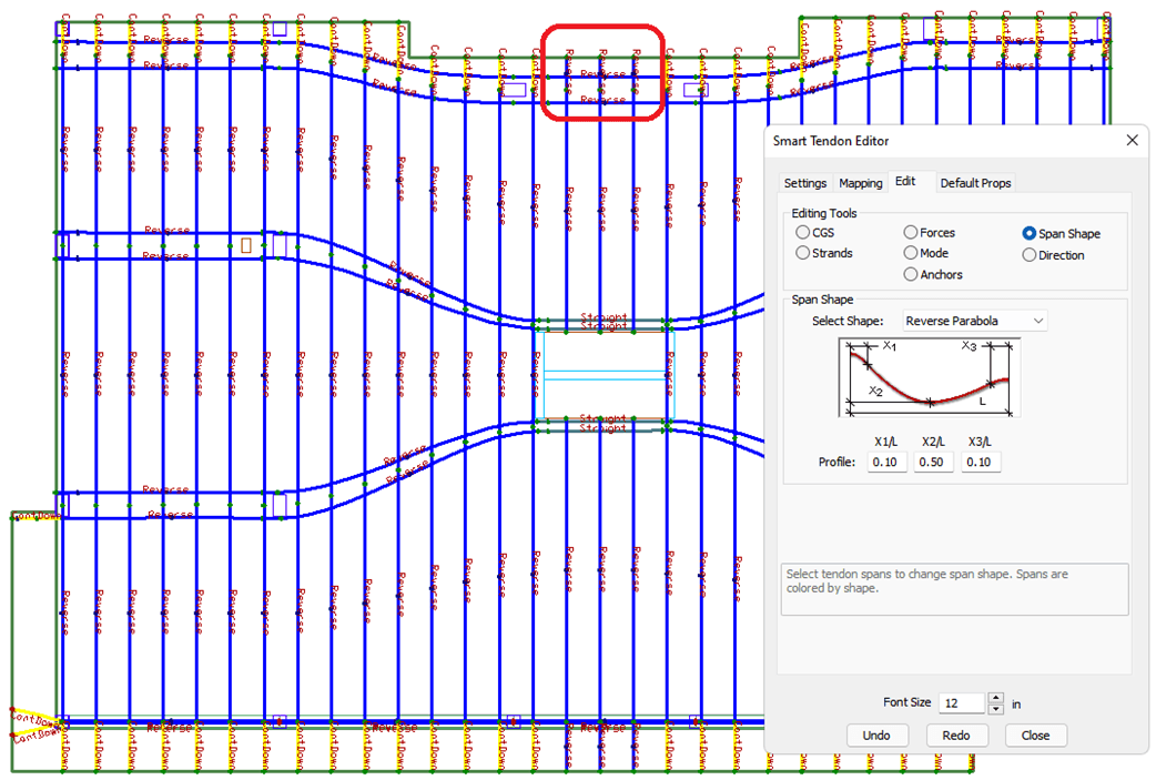
Looking at the area circled in red (above) we can see the tendon uses a Reversed Parabola profile. If an edit is required (ex. change to be Cantilever Down) as other tendons in this location show, we can use the Edit tab of the Smart Tendon Editor to set the "Span Shape" to "Cant. Down" and then draw a two point construction line over the tendons we want to modify (as shown below) to complete the modification.
The other options available in the Edit tab work in a similar fashion. This allows for quick on screen editing of all tendon properties adding efficiency to the process of laying out tendons in a model for the user.
For more information on the tendon tools and specifics on each element within the Smart Tendon Editor, visit the ADAPT-Builder Help File or check out the video below.

Modeling complex structures in any structural analysis and design...
Reinforced and post-tensioned concrete structures in today's...
ADAPT-Builder includes a Support Line Span Optimizer that allows the...