


 By: Admin
Include Transfer Forces in Vertical Brace Connections
RISAConnection assumes by default that your vertical brace connection...
With the new RISAConnection version 2.0, users now have the ability to design all connections for axial forces as well as the shear and moment forces.
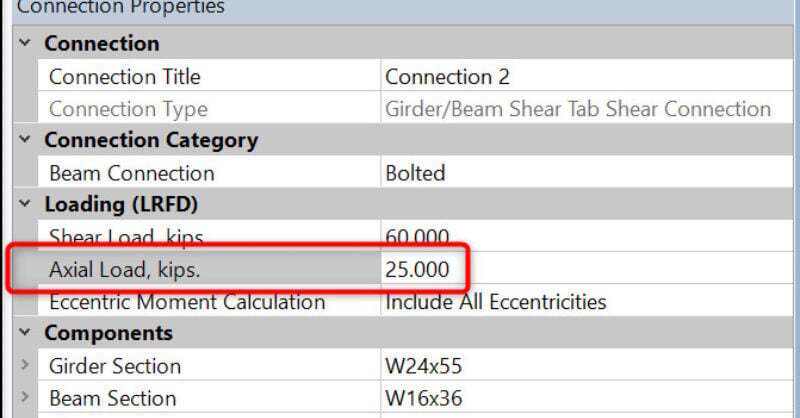
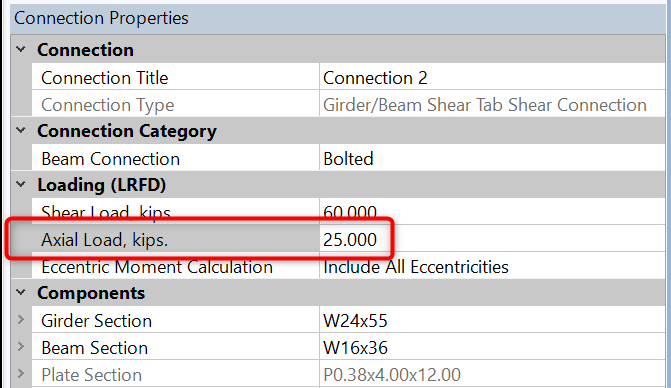
For beam to column or beam to beam connections, simply enter your axial force under the Loading section of the Connection Properties dialog.
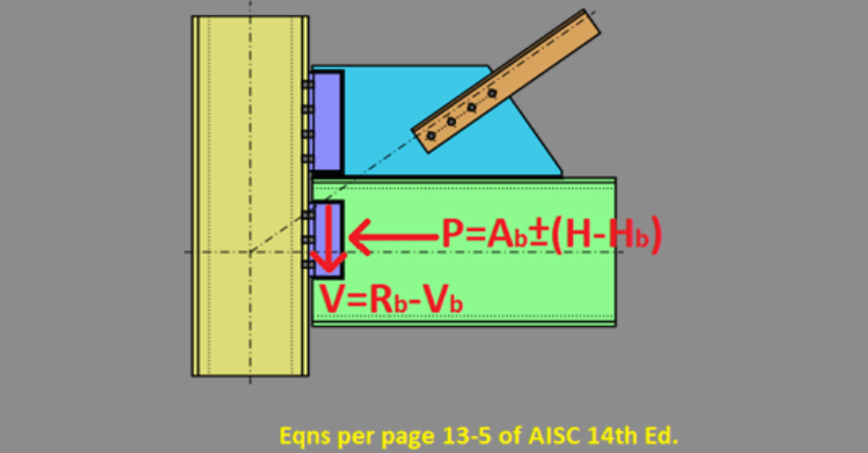
For vertical brace connections, enter the beam axial force as the Beam Axial Load entry under Loading, and the brace axial force as Brace Axial load.
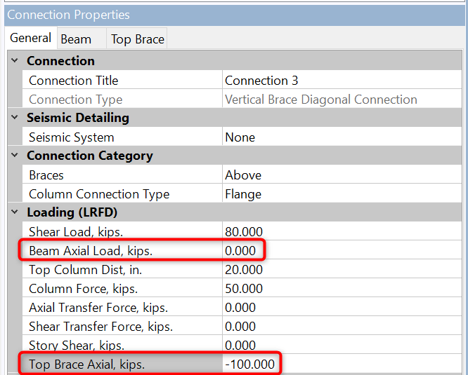
RISAConnection uses the same sign convention as RISA-3D and RISAFloor. This is so the loads transfer properly if you are utilizing the program integration. Compression forces are positive (+) and tension forces are negative (-).
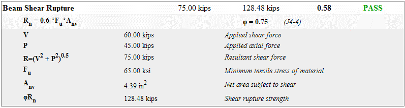
To account for axial loads and shear loads, RISAConnection will often take the resultant of these two as the available load to compare to the capacity. This can expand the limit states checks. In cases where the axial load is less than 5% of the shear load, the axial load will be assumed to be zero and the limit states will look identical to that in version 1.1.
Axial loads in moment connections are considered through the flange forces only. When axial load is included, moment connection flange forces are calculated as:
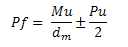
These flange forces are then compared to the capacity of each limit state for the unity value.
The axial loads will be accounted for in the output report. Each limit state may handle the axial load differently, so please see each limit state for more information and the Help file for further detail.
RISAConnection assumes by default that your vertical brace connection...
The most recent release of AISC 360-16 (15th Edition) includes changes...
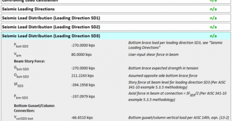
Seismic brace connections are a bit different from other connection...