Why Is My Beam Failing in Shear?
When solving a RISA-3D model you may find you have a Shear UC (unity...
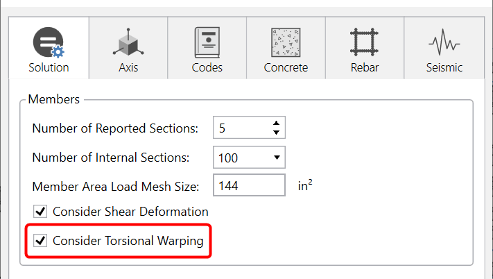
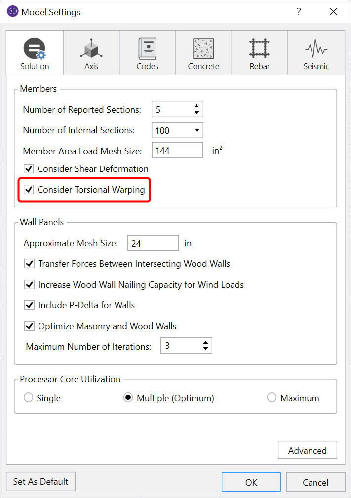
Twisting of a member or frame induces torsional forces and stresses. This is included in the RISA-3D analysis as long as you have the Torsional Warping checkbox selected on the Solution tab of (Global) Model Settings.
The primary reference used in the development of RISA-3D’s torsional calculations was the AISC Design Guide #9, Torsional Analysis of Structural Steel Members.
It is important to remember that RISA-3D models warping members using CASE 2 only. As shown in the Torsion reference, CASE 2 represents the torsionally fixed and warping fixed end conditions for the member. Thus, a member would be then subjected to an equal and opposite point torque at the end of the member.
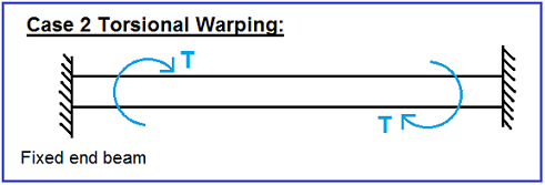
Note: RISA’s calculation of torsion stresses is good for capturing the torsion due to racking of the structure, not point or line torques on an individual member. That type of check is not supported.
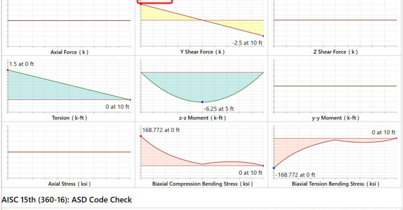
RISA-3D calculates and lists the torsional stresses for the members of the structure, including the warping stresses. These are reported in the Member Torsion spreadsheet.

For warping shapes (I’s and C’s), three separate stresses are calculated: pure torsion shear, warping shear and warping normal (bending) stresses.
These torsional stresses are included when the AISC code check (ASD or LRFD) is calculated for the member. The shear stresses (pure torsion and warping) are included in the shear check and the warping normal stresses are added to the weak axis bending stresses for calculation of the combined code check. For more information about how RISA-3D includes the shear stresses in the steel beam design, visit the article linked below:
When including shear stresses from torsion in the shear code check, the program uses the worst case of the torsional shear stresses (top and bottom flanges or web) and combines that with the actual shear stresses due to pure flexure. This is intentionally conservative in cases where the worst case torsional shear occurs in the flange, but the worst case flexural shear occurs in the web.
When solving a RISA-3D model you may find you have a Shear UC (unity...
RIAFloor designs the gravity system and then integrates with RISA-3D to...
Over the last few weeks, we have been working hard to add the features...