


 By: RISA
What is a Rigid Link in RISA-3D?
A rigid link is a member element in RISA-3D that can be used for many...
Rigid diaphragms in RISA-3D are a powerful way to model how floor systems distribute lateral loads. By forcing all connected nodes to move together in-plane, they effectively capture the stiffness of a concrete slab or diaphragm deck—often simplifying analysis without sacrificing accuracy.
However, when rigid diaphragms are combined with sloping members, they can introduce unexpected behavior that changes how the structure resists loads—sometimes creating a hidden “tension tie” that doesn’t exist in the real system.

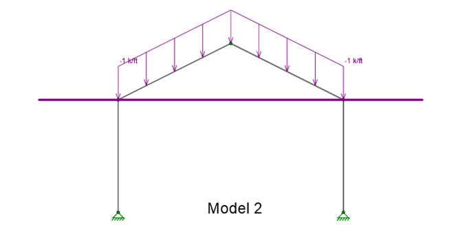
Consider a simple moment frame with sloped beams under gravity loads—common in pre-engineered metal buildings.


Model 1: No rigid diaphragm applied
Model 2: Identical frame, but with a rigid diaphragm located at the eaves
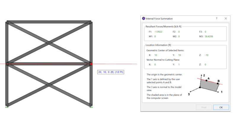
When reviewing the strong-axis bending moments, column base reactions, and thrust forces:


The first frame behaves as expected.
The second frame (with the rigid diaphragm) shows reduced bending moments and smaller thrust reactions at the column bases.
At first glance, this might seem like an improvement—but it’s actually unrealistic behavior caused by the diaphragm.
In the model with the rigid diaphragm, the diaphragm prevents the eaves from moving apart under load. This effectively turns the diaphragm into a tension tie between the eaves.
Under typical conditions (no rigid diaphragm), the eaves drift slightly apart. When the diaphragm is added, that movement is restrained, inducing compression in the sloped roof beams.


In other words, the structure is no longer acting purely as a moment frame—it’s behaving more like a truss, with the diaphragm acting as the bottom chord.
This unintended constraint alters load paths, changes axial forces in the beams, and can lead to underdesign if not recognized.


If your structure doesn’t include a physical tension tie, avoid using a rigid diaphragm in this way. But you may still need to represent diaphragm behavior for load distribution and stability.
Here are a few modeling options:
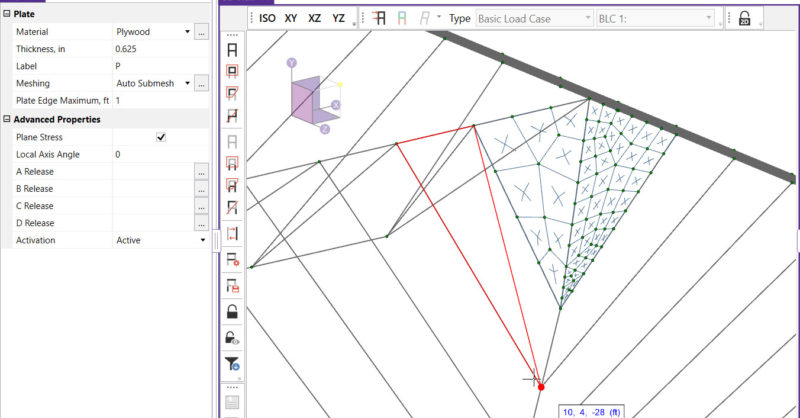
Use submeshed plates: Plate elements can be sloped to match the roof geometry while still providing diaphragm stiffness.
Model horizontal bracing: In some cases, bracing or “dummy” bracing can provide sufficient in-plane restraint without unrealistic stiffness.
When modeling plate and member elements together, be mindful of their interaction. This article provides further guidance:
👉 Understanding Plate and Member Interaction in RISA
Rigid diaphragms are extremely useful—but only when applied to structures that behave rigidly in-plane. When used on sloped framing systems, they can introduce unintended tension-tie behavior that alters how loads are distributed.
Always confirm that your diaphragm assumptions match the actual physical behavior of the structure you’re designing.
A rigid link is a member element in RISA-3D that can be used for many...
When using rigid diaphragm analysis in RISA-3D it can be useful to...
In standalone RISA-3D models (those not integrated from RISAFloor),...