


 By: Admin
Consideration of Drop Caps and Drop Panels for Punching Shear Design
ADAPT-Builder v22 now includes the ability to model a Drop Cap and a...
In the design of two-way post-tensioned slabs, whether it be by use of unbonded or bonded tendons, precompression or “average minimum precompression,” is a critical serviceability requirement in ACI318. It is used to serve as a means for selecting a prestressing force and/or quantity of tendons and also directly addresses the serviceability of column-supported floor systems and the need for minimum reinforcement for shrinkage and temperature.
The intent of minimum precompression is satisfied through use of crack control or total reinforcement for other major design codes, hence, a minimum limit for precompression is not required. These other design codes meet a similar need by stipulation for minimum reinforcement versus use of minimum precompression. In theory, a combination of non-prestressed reinforcement and prestressed reinforcement can satisfy code minimum requirements. It is the entirety of prestressed and non-prestressed reinforcement and proper distribution that guarantees satisfactory service-level performance of a two-way post-tensioned slab.
For designs conforming to ACI318, where precompression delivered to the slab through prestressed reinforcement meets the minimum requirement of 100psi (0.69MPa), this is deemed acceptable in lieu of non-prestressed reinforcement. Other requirements related to spacing are also necessary to be met. If they are not, a combination of prestressing and non-prestressed bonded reinforcement is necessary.
ACI318 requires specific provisions be met related directly to prestressed slabs. One such provision is a minimum average precompression of 125psi for two-way slabs where the commonly used banded-uniform tendon arrangement is used. Historically, this level of precompression was found to enhance the performance of punching shear in two-way flat slabs based on tests conducted with this level of precompression. Thus, the requirement threshold of 125psi (0.85MPa) was added as a code requirement. This value is commonly used in design today as the minimum average precompresssion. Expressions used for determination of two-way shear strength consider slabs with and without precompression are used in today’s design code.
For compliance with the intent of ACI318 for minimum average precompression of two-way slab, separate from requirements for satisfying ultimate demand and necessary reinforcement for control of initial tensile stress at force transfer, the following applies:
The total area of prestressing strands meets a minimum precompression of 125psi (0.85MPa), or its equivalent expressed as:
The total area of prestressed and non-prestressed reinforcement in each design section of a design strip, satisfies the shrinkage and temperature requirements.
Where no prestressing strands are present, the reinforcement in each design section shall meet the following code conditions:
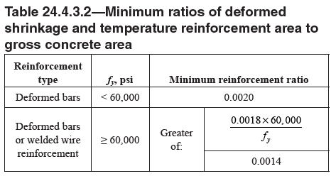
Where prestressing strands are used, the reinforcement ratio should not be less than [(As + Aps*(fpy/fy)] / Ac ⩾ Min reinforcement ratio specified in Table 24.4.3.2.
The average precompression is typically taken with reference to a hypothetical design section and not a point or punctual location. For application to the Equivalent Frame or Finite Element Methods of analysis and design, design sections for two-way PT slabs are oftentimes produced over the full tributary of a frame or column line and associated with a “design strip.” In reality, the precompressive stress at a point varies from location to location and can drop significantly at discontinuities.
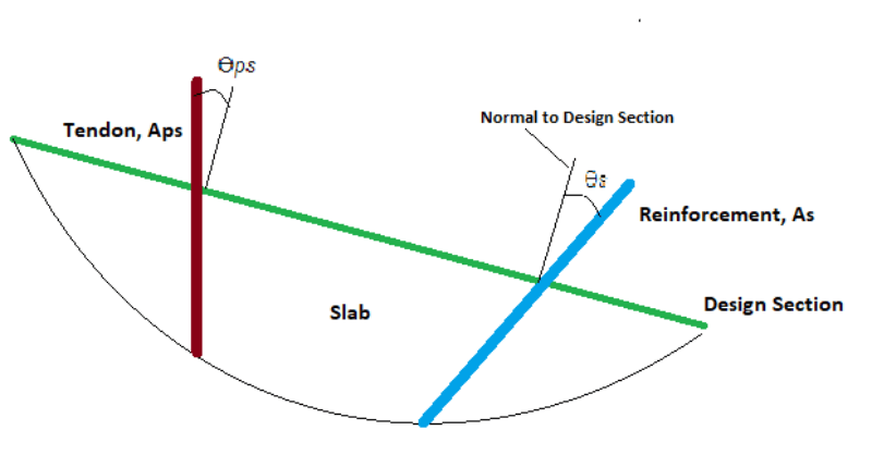
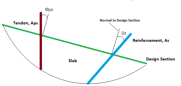
With respect to design sections having prestressing strands deliver the entire requirement for P/A (125psi or 0.85Mpa), the effective area of the prestressed reinforcement is considered. Where a mix of prestressed and non-prestressed reinforcement is used, the effective area of both is considered. For compliance to ACI318, prestressing strands often deliver the entire need for precompression. Therefore, the calculation of P/A is taken as:
P / Aps * cos ϴps where P = the total effective or calculated prestressing force and Aps = the total area of prestressing strands
Where non-prestressed reinforcement is used the effective area of reinforcement is considered as As * cos ϴs
In ADAPT-Builder, a finite element software for the analysis and design of prestressed and non-prestressed slabs and beams, there are two methods by which the precompression is checked for two-way post-tensioned slabs. These two methods are referred to as Number of Tendons Method and Finite Element Method - FEM. Both methods are described in more detail below. In short, the FEM option considers in-plane restraint and the loss of precompressive force due to boundary conditions, in-plane stiffness, and other factors causing loss or increase of force along the path of a design strip.
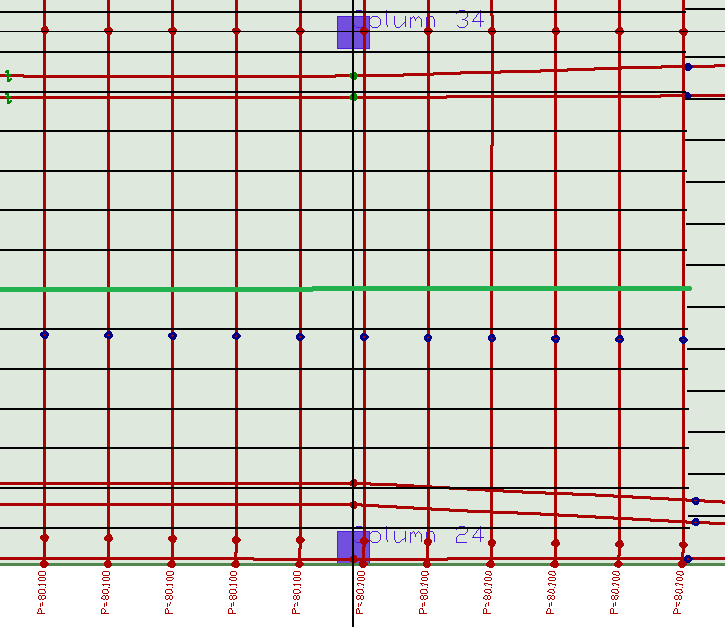
Number of Tendons Method - For this method, the program does not use the axial force calculated per nodal integration over the design section length. Rather, the program uses the sum of the prestressing force (effective or calculated as assigned by the user in the tendons properties) with respect to the angle ϴ, measured between the design section face and an axis normal to the section face. Where the angle is 90 degrees the full effective or calculated force is taken.
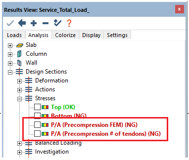
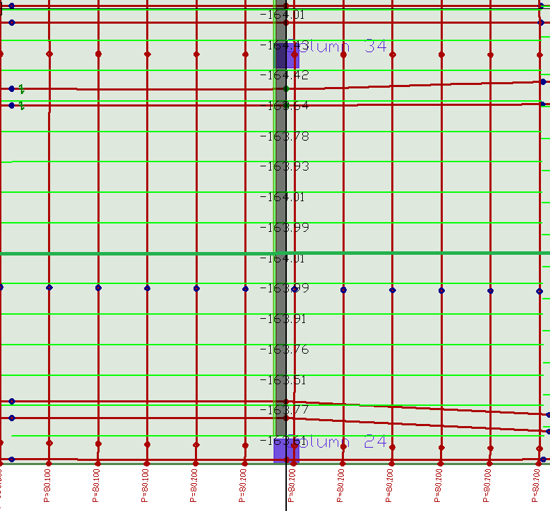
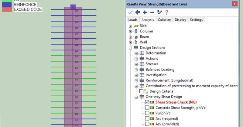
In the example below, the design section highlighted at green is being checked. The area of this section is taken as its thickness*length. This is equal to 5362in2. The total force intersecting the section is the total sum of force over area. The total force for each tendon line is shown at the bottom of tendons. The sum is taken as 80.1k * 11 tendons = 881.1*cos 0 = 881.1k. P/A (No. Tendons) = 881.1k / 5262in2 = 0.164ksi (164psi). The 2nd image below shows the graphically reported value as the same
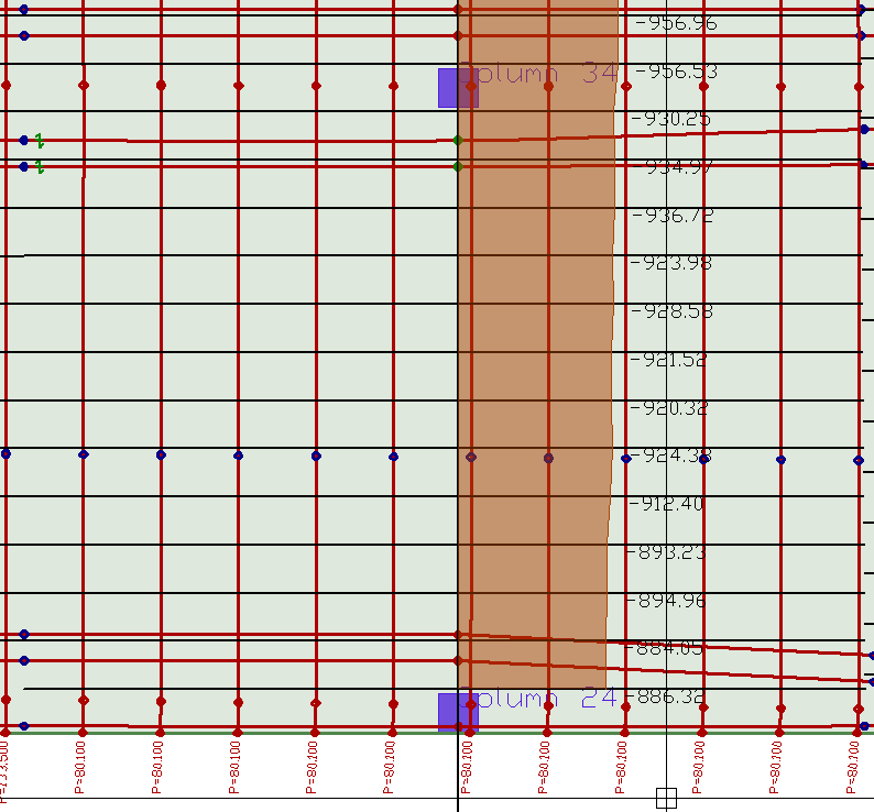
Finite Element Method - FEM - For this method, the program uses the axial force calculated per nodal integration over the design section length. The force calculated is affected by the distribution of forces subject to in- and out-of-plane element stiffness. When used properly, this method can be a valuable tool in capturing the loss of prestressing force due to undesirable wall and support layouts, placement of pour strips and wall fixity to slabs.
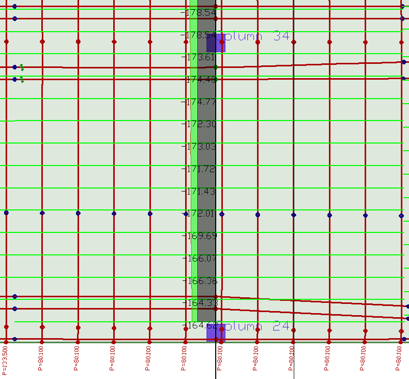
For this method the location and orientation of the prestressing tendons and how forces shed in both slab directions is inherent to the solution. For calculation of the precompression, the layout and placement of the design strips and design sections is critical. The axial force calculated using integration of shell forces over the section length is divided by the section area. In the previous example, the same section area is considered (5362in2). The axial force at the same design section is reported as 920.32k. P/A is then calculated as 920.32k / 5362in2 = .171ksi. The 2nd image below shows the graphically reported value as the same.
In both methods, it should be noted that the program graphically code checks against a user-defined minimum value. The default for ACI318 being 125psi (0.85MPa). Where the minimum precompression value does not meet the code required limit of 125psi, it should be noted that the program does not add non-prestressed reinforcement necessary to meet the requirements directly related to minimum reinforcement for temperature and shrinkage. Other “minimum” service requirements specific to two-way prestressed slabs are considered. Namely, minimum reinforcement at supports (0.00075*Ac) and at positive bending regions where stress exceeds 2*sqrt(f’c).
Aside from the replacement of minimum bonded reinforcement, control of flexural stresses and deflection, and crack control, there are other advantages to precompression delivered by prestressing strands that include, but are not limited to:
the use and reduction of axial forces and moments in chords and collectors of diaphragms where lateral forces are being delivered to the lateral resisting system elements,
the increase in two-way concrete shear capacity of slabs
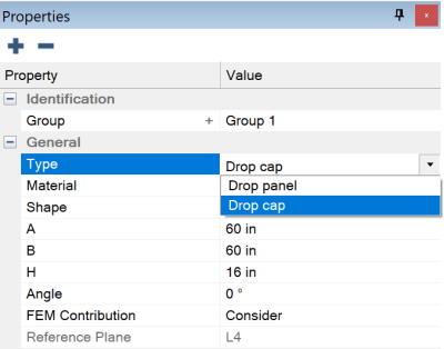
ADAPT-Builder v22 now includes the ability to model a Drop Cap and a...
The ability to quickly evaluate results and make data-based design...
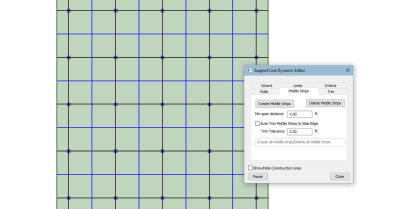
A key feature to the design process for two-way slabs, either RC or...