 Admin
Admin
What are the Unbalanced Forces on Beams?
V-Brace frames in RISA-3D seismic design have unbalanced forces shown on both the beams and braces. As brace frames displace under lateral loads,...
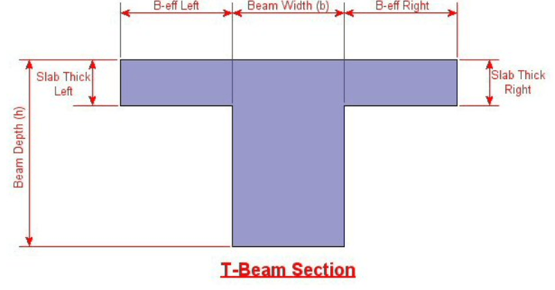
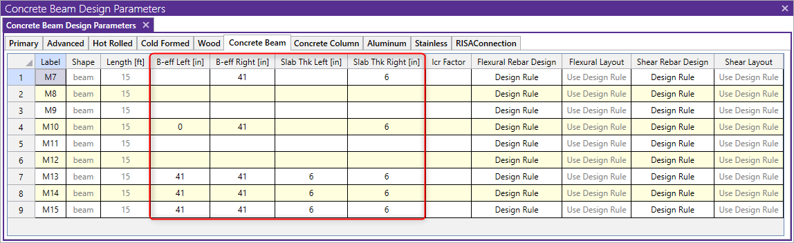
Modeling T-beams and L-beams in RISA-3D can easily be done by specifying the flanges after drawing in the rectangular concrete beam. The flange properties can be specified for individual members on the Concrete Beam tab of the Members spreadsheet, or for a group of selected members in the Properties dialog.
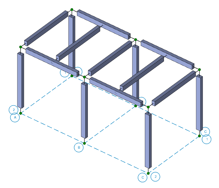
1. First, draw in the beams as regular rectangular concrete sections.
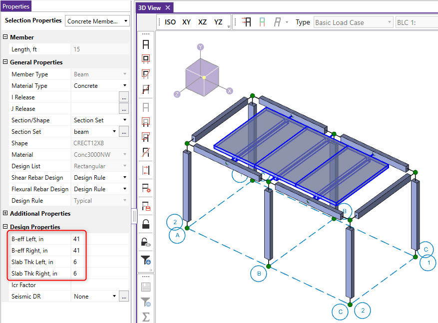
2. Next, select all of the intermediate beams which should be T-beams. You can click and drag over them to do this or hold CTRL+click each beam.
3. Enter in the appropriate Effective Slab Widths and Slab Thicknesses.
4. Similarly enter in the Eff Widths and Slab Thickness values for just one side to create the L-Beams.
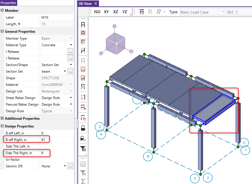
Alternatively, you can modify these entries in the Concrete Beam tab of the Members spreadsheet.
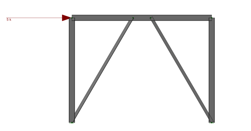
V-Brace frames in RISA-3D seismic design have unbalanced forces shown on both the beams and braces. As brace frames displace under lateral loads,...
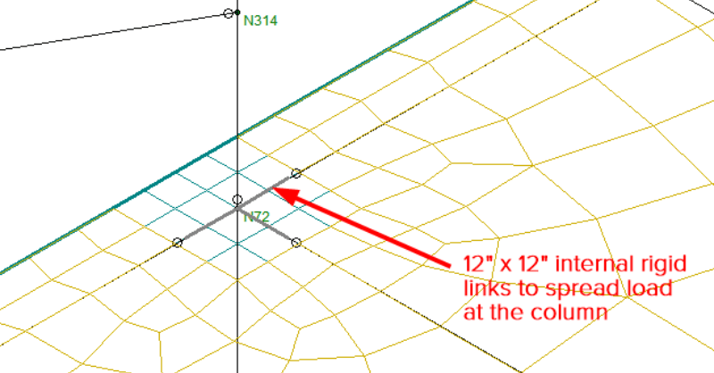
When using semi-rigid diaphragms in a RISAFloor/RISA-3D model, it is possible to see negative moments at the ends of pinned beams as a result of...
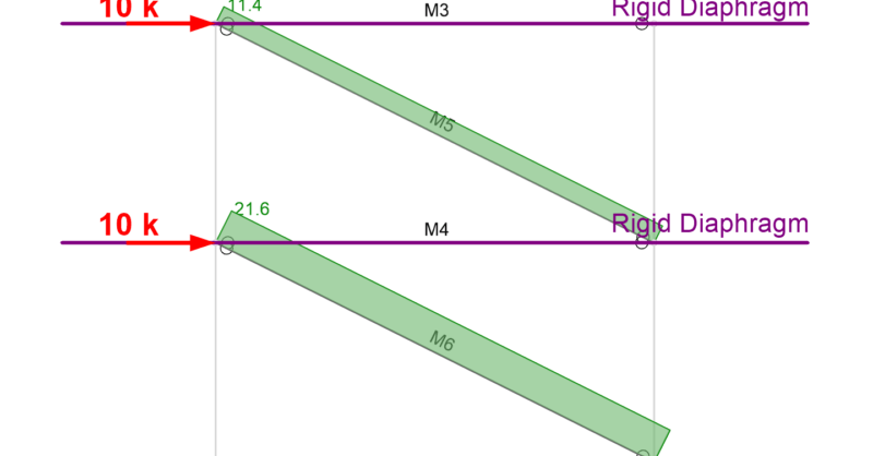
The beams in a lateral force resisting system, such as a braced frame or moment frame, typically carry a significant axial force. In the example...