 Admin
Admin
1 min read
Seismic Design of Masonry Walls (TMS 402-16) in RISA-3D
RISA-3D is expanding its industry leading support for the analysis and design of various materials with the implementation of Seismic Design of...
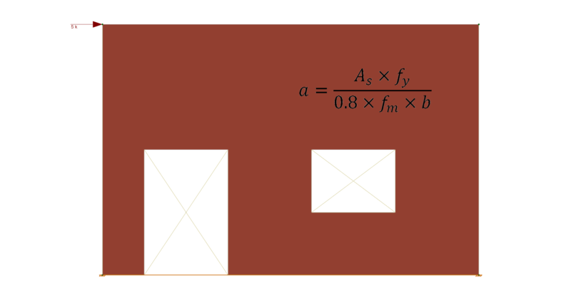
When determining the Depth of Compression Block value of ‘a’ in a Masonry Wall design based on the equation a = (As * fy)/(0.8 * fm * b) in a RISA-3D model, it is possible to see a small variance in the program results versus a traditional hand calculation using this typical equation. The reason for the slight difference will be explained in detail in this article.
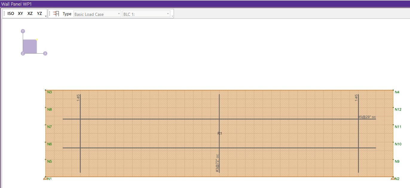
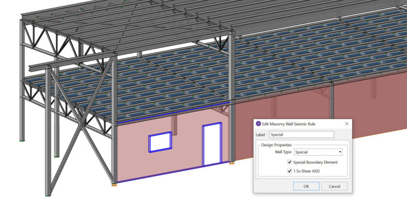
By first viewing the chosen masonry wall layout for WP1 in the Wall Panel Editor, as depicted below, there is an applied basic load case BLC 2: 1 k/ft distributed load applied in the Global X direction across the top of the 40’-0” long wall.
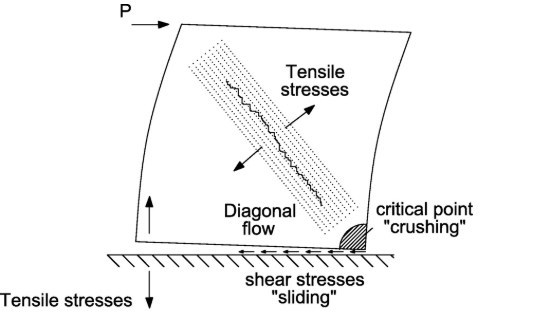
In theory the applied load causes the vertical reinforcement on the masonry walls tension side to try and help the vertical reinforcement on the masonry walls compression side to resist the lateral force, P, and behave as shown in the graphic below.
As shown in the sketch below, this can be expressed by mathematical representation of the stress-strain relationship to determine the tension and compression couple.
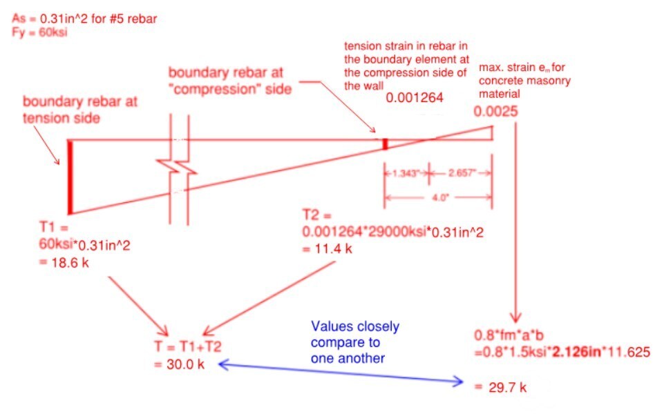
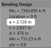
The program is considering the rebar on the compression side of the wall to contribute to the total rebar tension, because it actually doesn't fall into the compression zone if we study the stress-strain relationship. That's why if we use the simple hand calculation equation for the depth of the compression block, a = (As * fy)/(0.8 * fm * b), when using a small vertical reinforcement bar such as (1) #5 [As = 0.31 in^2] in a 12 inch nominal width concrete block, the value of ‘a’ doesn't match the program's result very close as explained further by comparison. The depth of the compression block by hand calculation is: a = (0.31 in^2 * 60 ksi)/(0.8 * 1.5 ksi * 11.625 in) = 1.333 inches. This value is approximately 60% smaller in comparison to the programs result for depth of the compression block, a = 2.126 inches.
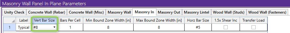
With this being said, if you go to the Masonry Wall Panel In-Plane Parameters and increase (1) #5 to larger (1) #8 vertical reinforcement bar, you can get 'very close' to a hand computation for the depth of compression block 'a', within a reasonable margin of difference.
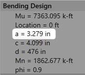
Using the same RISA-3D masonry wall model, and increasing to a larger vertical reinforcement bar such as (1) #8 [As = 0.79 in^2] in a 12 inch nominal width concrete block, the depth of the compression block by hand calculation is: a = (0.79 in^2 * 60 ksi)/(0.8 * 1.5 ksi * 11.625 in) = 3.398 inches. This value is approximately 3% larger in comparison to the programs result for depth of the compression block, a = 3.279 inches.
The masonry wall panel element allows you to easily model, analyze and design masonry walls for in plane and out of plane loads. To learn more about the design rules for Masonry Wall Panels, visit the Help section linked below.

1 min read
RISA-3D is expanding its industry leading support for the analysis and design of various materials with the implementation of Seismic Design of...
The new TMS 402-16 Masonry Code (formerly designated as ACI 530 and ASCE 5) have been added to RISA-3D v16.0, RISAFloor v12.0 and RISAFoundation...
In RISA-3D, the current method of design for masonry lintels is Simply Supported where the masonry lintels are idealized into a simply supported...